CAN BUS ON STM32
Preface
Controller Area Network (CAN or CAN bus) is a feature-rich automotive bus standard designed to allow single-chip devices and instruments on a network to communicate with each other without the need for a host. Based on a message-passing protocol, it was initially adopted in vehicles to reduce the amount of copper wire used by multiplexing communication cables, and has since been used in other industries. Under the master’s thesis, the dsPIC30F4011 (Microchip) chip was used to implement the CAN bus system. Now, research has begun on the operation of the STM32 CAN Bus due to customer demand. This article will introduce the wiring and example code for operating the CAN bus.
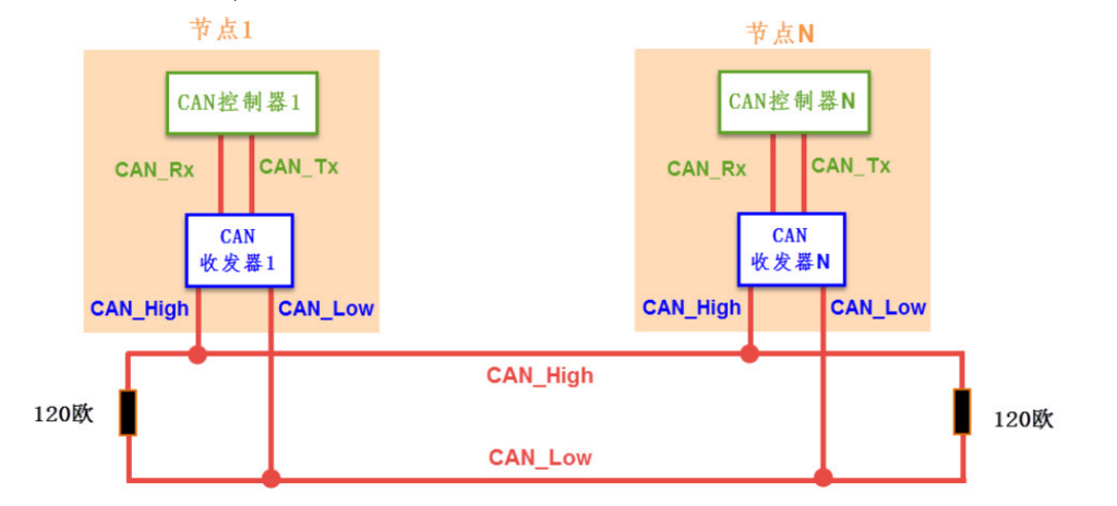
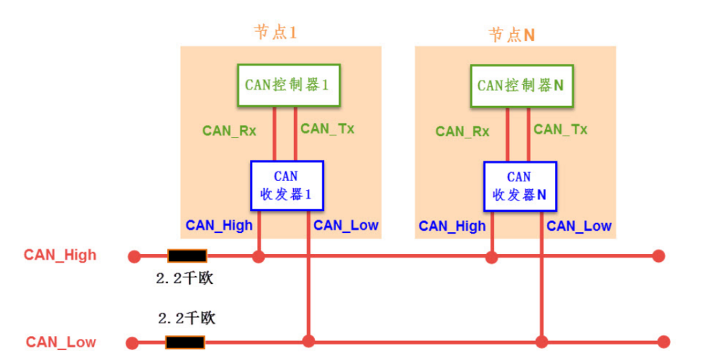
Can Bus wiring


- The CAN communication network on the left is a high-speed, short-distance “closed loop network” that follows the ISO11898 standard. Its bus length can be up to 40m, with a maximum communication speed of 1Mbps. Each end of the bus requires a “120 ohm” resistor.
- The one on the right follows the ISO11519-2 standard and is a low-speed, long-distance “open loop network”. Its maximum transmission distance is 1km, with a maximum communication speed of 125kbps. The two buses are independent and do not form a closed loop, and each bus requires a “2.2 kohm” resistor to be connected in series.
PS:that when wiring the hardware, it is important to add resistors and a CAN transceiver, and not to connect the MCU’s Can pins directly.”
MESSAGE TRANSFER
CAN 2.0 has two versions, CAN 2.0A (Standard) and CAN 2.0B (Extended).

- Start of Frame (SOF): sends a 1-bit dominant (0) to synchronize.
- Arbitration Field: represents the node’s priority and is used to determine priority. If multiple nodes transmit at the same time, the arbitration field compares priority bit by bit, and the bit that is dominant (0) can transmit first. There are two lengths, 11 bits (Standard Identifier) and 29 bits (Extended Identifier).
- RTR :identifies whether data is to be transmitted or received. RTR=dominant(0) indicates data is to be transmitted, and RTR=recessive(1) indicates data is to be received.
- IDE: Standard Format (Standard Identifier) is dominant (0); Extended Format (Extended Identifier) is recessive (1).
- R0:Reserved.

Transmission diagram on the CAN bus
As shown in the diagram below, there are three transmission devices, A, B, and C, which will simultaneously put data on the bus line. Here, it is only necessary to pay attention to giving a small delay time for each device during transmission to avoid overlapping conflicts in data transmission.

STM32cubeMX Setting and Sample code

How to set the baud rate?
Example 1: If we want to set the baud rate to 500KHz, we can set it as follows (using the formula below).
Fpclk1/((CAN_BS1+CAN_BS2+1)*CAN_Prescaler)=42M/(4+2+1)/12=500kHz

Basic Parameter Setting
- Timer Triggered Communication Mode:Whether to use the Time Triggered Transmission (TTT) function (ENABLE/DISABLE), which is used in some CAN standards.
- Automatic Bus-Off Management:Used to set whether to use the automatic Bus-Off management function (ENABLE/DISABLE). Using automatic Bus-Off management, the system can automatically recover from errors without software intervention.
- Automatic Wake-Up Mode:Used to set whether to use the automatic wake-up function (ENABLE/DISABLE). Enabling the automatic wake-up function will automatically wake up the system when bus activity is detected.
- Automatic Retransmission:Used to set whether to use the automatic retransmission function (ENABLE/DISABLE). When using automatic retransmission, messages will be continuously transmitted until they are successfully sent.
- Receive Fifo Locked Mode:Used to set whether to use the locked receive FIFO function (ENABLE/DISABLE). When the receive FIFO is locked, new data will be discarded if the FIFO overflows, otherwise new data will overwrite old data in case of FIFO overflow.
- Transmit Fifo Priority:Used to set the priority determination method for transmitting messages (ENABLE/DISABLE). When enabled, messages will be transmitted in the order they were stored in the transmit mailbox, otherwise they will be transmitted according to the priority of the message ID.
Types of Interrupts
- RX0, RX1 Interrupts: STM32 has two 3-level depth receive buffers, FIFO0 and FIFO1, each of which can store up to 3 complete messages, which are fully managed by hardware. If the interrupt is from FIFO0, it is handled by CAN1_RX0_IRQn interrupt. If the interrupt is from FIFO1, it is handled by CAN1_RX1_IRQn interrupt.
- SCE Interrupts:Status Change Error, error and status change interrupt.
Sample code and Function
Here we take the F4 series as an example, for other series, please refer to the User Manual.
Open CAN Bus
HAL_CAN_Start(&hcan1);
Send Data
uint8_t bsp_can1_send_msg(uint32_t id_type,uint32_t basic_id,uint32_t ex_id,uint8_t *data,uint32_t data_len)
{
    uint8_t index = 0;
    uint32_t *msg_box;
	uint8_t send_buf[8] = {0};
    CAN_TxHeaderTypeDef send_msg_hdr;
    send_msg_hdr.StdId = basic_id;
    send_msg_hdr.ExtId = ex_id;
    send_msg_hdr.IDE = id_type;
    send_msg_hdr.RTR = CAN_RTR_DATA;
    send_msg_hdr.DLC = data_len;
	send_msg_hdr.TransmitGlobalTime = DISABLE;
	for(index = 0; index < data_len; index++)
          send_buf[index] = data[index];

    HAL_CAN_AddTxMessage(&hcan1,&send_msg_hdr,send_buf,msg_box);
    return BSP_CAN_OK;
}
Get Data
uint8_t bsp_can1_polling_recv_msg(uint32_t *basic_id,uint32_t *ex_id,uint8_t *data,uint32_t *data_len)
{
	uint8_t index = 0;
	uint8_t recv_data[8];
    CAN_RxHeaderTypeDef header;

  while (HAL_CAN_GetRxFifoFillLevel(&hcan1, CAN_RX_FIFO0) != 0)
  {
    if (__HAL_CAN_GET_FLAG(&hcan1, CAN_FLAG_FOV0) != RESET)
      printf("[CAN] FIFO0 overrun!\n");

    HAL_CAN_GetRxMessage(&hcan1, CAN_RX_FIFO0, &header, recv_data);
	if(header.IDE == CAN_ID_STD)
	{
              printf("StdId ID:%d\n",header.StdId);
	}
	else
	{
              printf("ExtId ID:%d\n",header.ExtId);
	}
	printf("CAN IDE:0x%x\n",header.IDE);
	printf("CAN RTR:0x%x\n",header.RTR);
	printf("CAN DLC:0x%x\n",header.DLC);
	printf("RECV DATA:");
	for(index = 0; index < header.DLC; index++)
	{
              printf("0x%x ",recv_data[index]);
	}
	printf("\n");
  }
}
Other Function


PS:Older versions may have HAL_CAN_Transmit and HAL_CAN_Receive. Newer MCUs have replaced them with the new library. You can refer to the following figure

