Detail Know How For MCSDK
Preface
Figuring out what constitutes good motor control and how to make adjustments has always been a challenge for many newcomers. Here, we’ll provide a detailed introduction with real-life examples and useful tools, starting from using Motor Pilot to detect motor parameters, then moving on to Open loop HW debugging, and finally transitioning to Close loop start-up, and more.
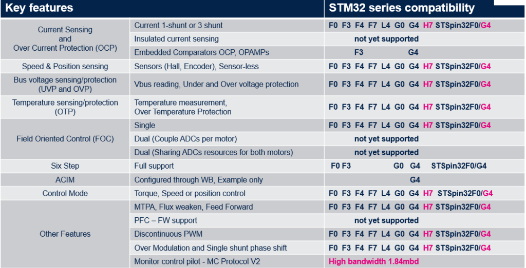
MC-SDK v6.1 – FW lib features list
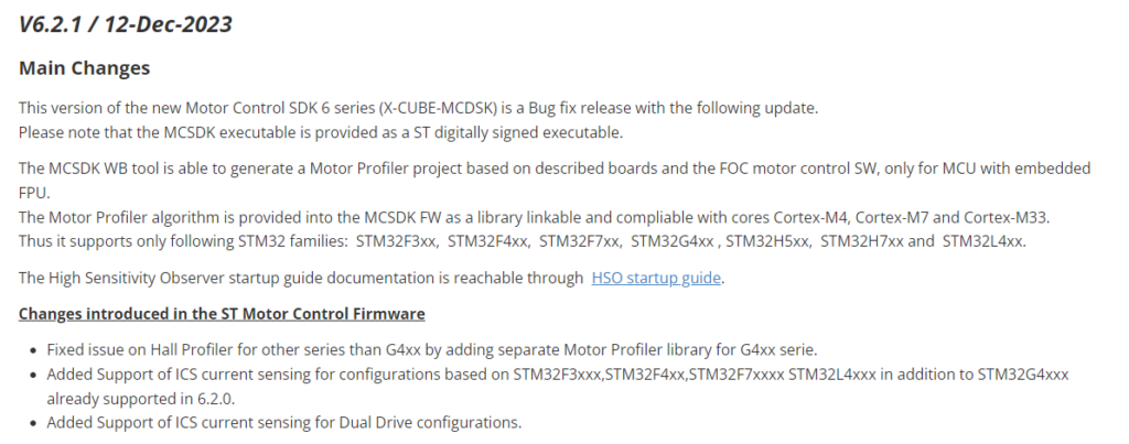
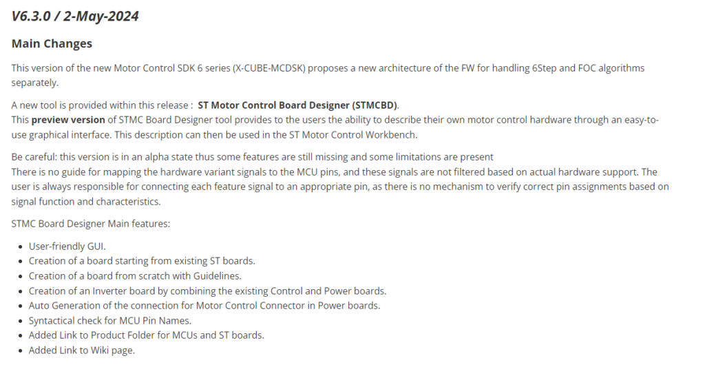
The latest version is currently 6.3, but the comparison table in the publicly available documents hasn’t been updated yet. The main differences are the addition of Dual Motor support and the inclusion of C0 and H5.
Motor profiler steps
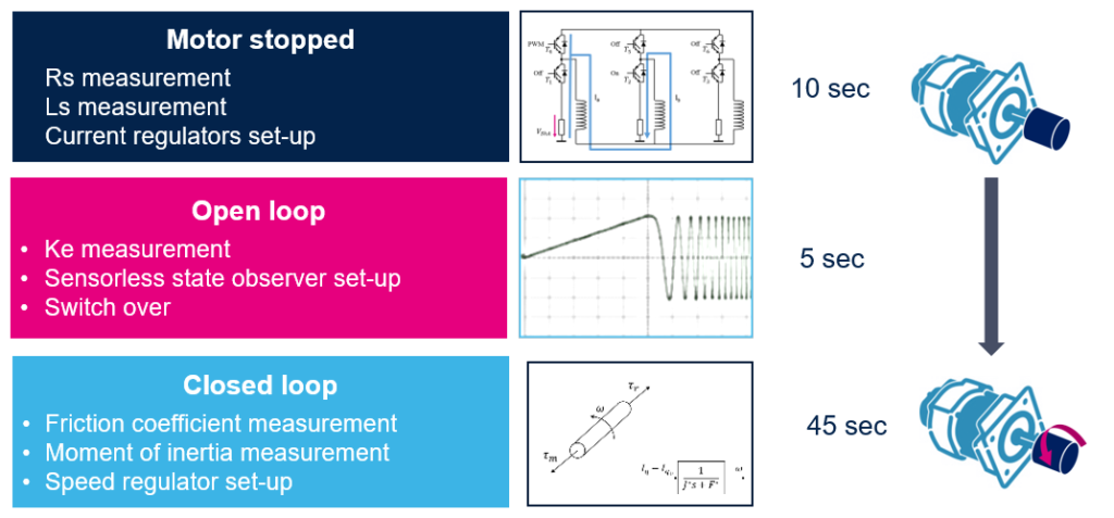
The operation will typically be completed within 1 minute. If it exceeds 1 minute, a failure may occur, and the failure is most likely to happen during the third stage. The most direct solution would be to reduce the maximum speed to allow the ST algorithm to complete or measure directly.
- In the first stage, Rs (stator resistance) and Ls (stator inductance) are measured by switching MOSFETs to assess the motor hardware.
- In the second stage, the system is set to open loop to measure Ke, the back electromotive force constant.
- In the third stage, based on the parameters from the previous steps, a closed-loop test is conducted to measure the motor’s maximum speed, friction coefficient, and moment of inertia.
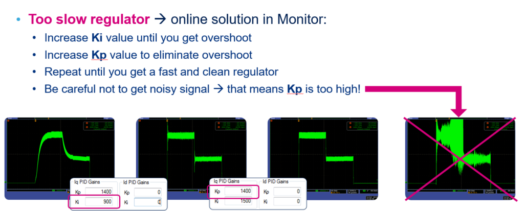
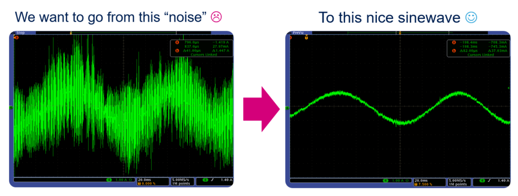
Checking the Current Regulator
Let’s first take a look at what is good and what is not.
Typically, Open Loop is used to first confirm and debug the hardware. The voltage setting generally doesn’t need to be much higher, about 10% should be sufficient.


Close Loop Speed Adjust For Kp KI
Let’s directly look at two results here, mainly focusing on whether the speed decreases too slowly or too quickly.

