

BLDC Six Step Control(Sensorless)
Preface
This section introduces the principles of six-step control.
The open-loop part is relatively simple, and most issues typically occur on the feedback side.
For sensorless feedback, we will refer to documentation from ST and NXP to provide detailed explanations.
This will help clarify the debugging process and save development time.
The coding structure will mainly follow ST’s framework, and implementation details will be covered in the practical section.
Six Step Control
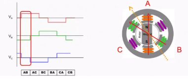
The typical six-step driving method involves switching the MOSFETs in six distinct combinations to achieve continuous motor rotation.

Here, we illustrate two of the six steps to help everyone understand how the rotation works.
In the first step, phase A has a positive voltage and phase B has a negative voltage. In this phase, the resulting magnetic force direction is shown as the orange dashed line (corresponding to the effect of this voltage step).
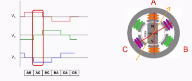
In the second step, phase A has a positive voltage and phase C has a negative voltage. In this phase, the resulting magnetic force direction is indicated by the orange dashed line (representing the effect of this voltage step).
Sensorless Feedback
The forward control part is generally straightforward; the main challenge lies in the latter stage feedback control (back EMF detection).
Commutation Timing
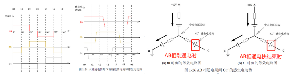
Since the midpoint potential remains at 6V, the back EMF generated by the CC’ coil can only be superimposed based on this 6V reference.
Assuming that a 5.7V back EMF is generated on CC’ at nominal speed, at time t0, if we measure the voltage at point C, the value should be 6 + 5.7 = 11.7V. At time t1, the voltage at point C would be 6 – 5.7 = 0.3V.
This means that during the AB phase conduction, if we continuously monitor the voltage at the motor’s C terminal, and it drops below 6V, it indicates the rotor has rotated 30°, reaching the midpoint between t0 and t1.
After waiting for another 30°, commutation can take place.
ADC Zero-Crossing Signal Acquisition
If the MCU in the ESC (Electronic Speed Controller) is fast enough, it can use continuous ADC sampling to measure the voltage at point C.
However, this approach can be somewhat wasteful, as most of the sampled ADC values are not useful — we’re only interested in the moment when it drops below 6V.
Although we can’t predict the exact duration of the upcoming 30° electrical angle, we can measure the duration of the previous commutation cycle, which spans 60° electrical degrees between two commutation points.
Therefore, an approximate method is to take half of the previous 60° cycle time as the delay for the next 30° electrical angle.
This approach is feasible because motor speed changes gradually, and the time difference between two adjacent commutation cycles is usually small.