Theory For FOC Control-1
Preface
We will be discussing the ‘Y-type winding brushless DC motor’, and will explain the motor type, principle of rotation, control methods, theoretical control, and step-by-step implementation.
are shown in the following figure.

Principle of Motor Rotation
The two circular magnets in the figure below will rotate due to the rotation of the upper magnet, causing the lower magnet to rotate due to the repulsion of like poles and attraction of opposite poles.


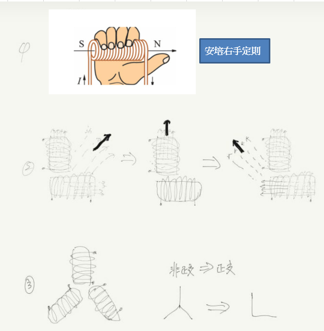
From the above, it can be known that when the magnets are perpendicular to each other (mathematically known as orthogonal), their force effect is the greatest. By changing the direction and magnitude of the current passing through the coil (as shown in the figure below), the direction of the resultant force can be made more diverse.
Rotational diagram
Motor rotation diagram in the textbook
Brushless motor rotation diagram


Here we can see that in the motor rotation diagram in the upper figure, the external part is a permanent magnet (stator), while the rotating shaft (rotor) is a coil. When the coil is energized and combined with the right-hand palm rule, it produces rotation. This structure is the conventional brushed DC motor.
And on the right-hand side, the coils are fixed (stator), and the rotating shaft is composed of permanent magnets (rotor), which is a typical brushless DC motor.
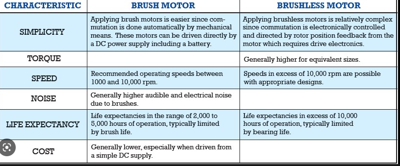
Comparison table between brushed DC and brushless DC motors
Control methods for brushless DC motors
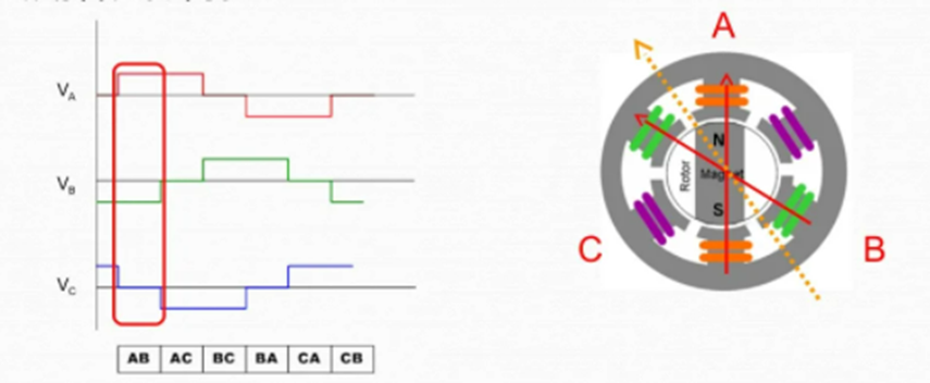
Six Step Square Wave
Here we simply divide the three voltage inputs into six segments and use different voltage inputs to make the motor rotate. (You can refer to BLDC FOC control principle for more information.)

Here we explain steps one and two, as shown in the diagram below. The combined magnetic field direction (yellow dotted line) of the two energized coils causes the rotor of the motor to rotate to that position, and so on, achieving continuous rotation

Field Oriented Control
Shown in the figure below, the concept is to control the motor using sine wave voltage. FOC control will be the main focus in the subsequent chapters, where we will delve deeper into its mathematical theory and introduce FOC control.