Theory For FOC Control-3
Preface

In the previous section, we discussed the decomposition of feedback signals. In this section, we will delve into the introduction of input signals.
PWM to SPWM
We need to drive a three-phase inverter circuit, and if we use only switching, we will get a control signal similar to a 6-step square wave, which is not smooth enough. Here, we want to make it smoother by introducing two concepts.
- PWM
- Area equivalence theorem.

PWM is believed to be familiar to those who control motors. Basically, the duty cycle and frequency of the operation voltage are controlled as shown in the figure below to achieve the effect of equivalent voltage.


From the above, we can advance further by converting all the sine waves into square waves as shown in the following figure.

This leads us to two types of control waveforms:


So far, we have learned about controlling the input PWM with a single-phase sine wave. The next step is to extend it to three phases to control BLDC.
Three-phase voltage control


From the diagram on the right, we can derive the equations shown in the diagram on the left, and then, from the three sets of bridge arms, we can obtain 8 combinations.

We take one of the states as an example, as shown in the figure below. We simplify it step by step from left to right until we obtain the simplified diagram on the far right.


From the above diagram, we can obtain the following equations.


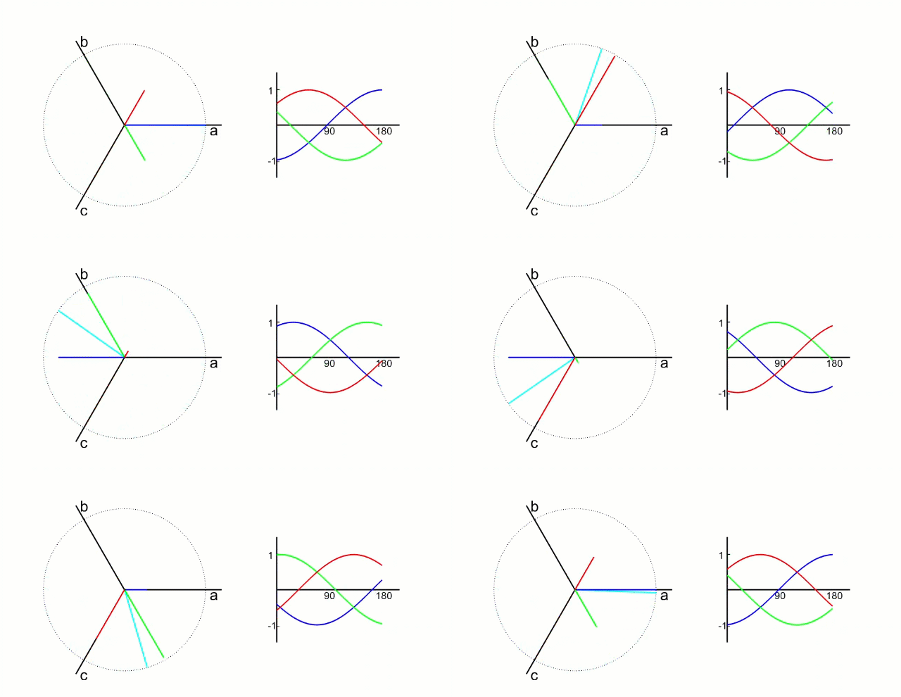
By deriving from one of the states shown in the previous diagram, we can obtain the following table of all states, which can then be graphically represented as shown on the right.


But the direction of the obtained diagram is different from the standard diagram given on the Internet. Here is the key point: the abc coordinate axis represents the direction of the space vector, which is called the three-phase stationary coordinate system, not the equivalent model of the motor. The vector on the motor model needs to be transformed into a vector on the three-phase stationary coordinate system, which requires a simple transformation – negative to positive, positive to negative, and a mirror flip after the transformation to match the internet diagram, as shown below.

Combining the vector combination with the concept of PWM, the next step is to combine them into SVPWM (Space Vector PWM), which has three main points as follows:
- The output voltage is generated by repetitively switching between two adjacent active vectors and the zero vector.
- The θ angle of the output voltage depends on the relative switching times of the two adjacent active vectors.
- The amplitude of the output voltage depends on the relative switching times of the two adjacent active vectors and the zero vector.
From the above calculations, we can obtain the time required for each switch, and thus we can achieve SPWM control. For more details, please refer to the analysis of SVPWM, detailed calculation of each sector, and Matlab simulation in the referenced article, which is very detailed.
