

Theory For FOC Control-4
Preface
After discussing all the mathematical transformations, we come to the final step of FOC control. First, let’s take a look at the Three Phase Inverter shown in the diagram below, which is generally included in the motor driver. The green box typically represents the MCU control calculation.

The final complete FOC algorithm
The physical meanings of Id and Iq mentioned in the previous chapter are to decouple the rotor magnetic flux into two variables, tangential and radial, which represent the rotational and radial components of the rotor flux, respectively.
- Iq represents the desired torque output we need
- while Id is the component we do not need and we try to minimize it as much as possible.

Next, we divide the control loop into three stages (current loop, speed loop, position loop) and add PI feedback compensation to obtain the following figure.
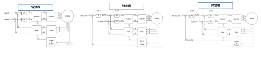
PS:In the speed control loop, the speed is not an instantaneous rate, but an average rate measured over a period of time. Therefore, if the speed is low, the average speed measurement method is not suitable because there will be significant errors (if the rotor is stationary or moving very slowly, the encoder will not output or only output 1 or 2 pulses).