

Position Controll(ext interface) on MCSDK6.x
Preface
Starting from MCSDK 6.x, position control can be generated directly, but currently only for standard encoders—others still require modifications. So how should we make these changes? We can explain this using a few examples. For interfaces like I2C or SPI, the implementation is mainly based on adapting ST-generated code, meaning only two control loops are used: position and current
Generate the FW and make the modifications
Since we’re using MCSDK 6.3.1, the process is essentially the same for all versions 6.x and above.
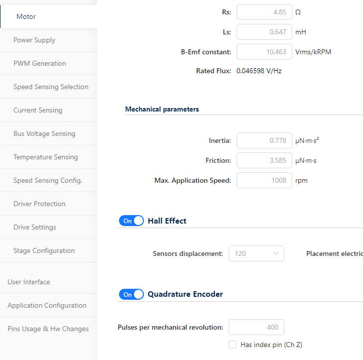
In the ST MCSDK settings, enable the Encoder option
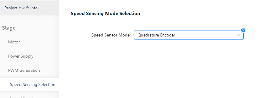
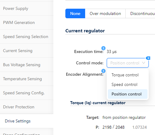
make sure to select position control in the following section.
Code Modification Logic
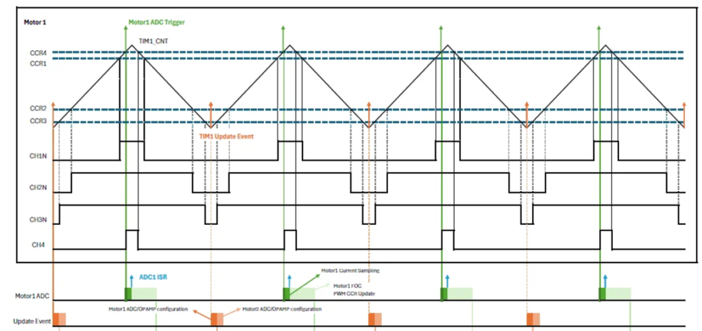
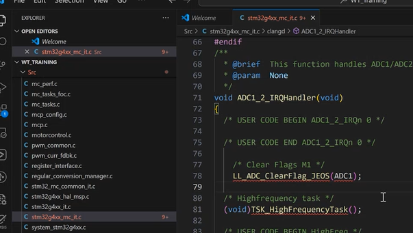
The first thing to confirm is how frequently your data is generated. Since PWM sampling is done at the peak of the cycle (as shown in the figure below), the computation must be completed within the same time frame. Otherwise, calculation errors may occur.
If the sampling is too slow, you’ll need to adjust the sampling frequency so that it’s not triggered on every rising edge. (Note: ST’s default setting samples on every cycle.)
In terms of code, the related section is as follows:
This part handles current loop triggering.
After sampling, it proceeds to update.
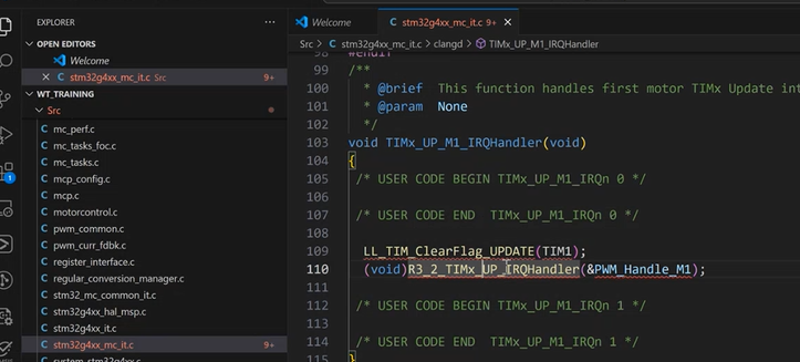
The computation for position control is mainly done in the medium frequency task, so it’s critical to ensure that all data is sampled and processed within one cycle.
(For example, at 30kHz, all tasks must be completed within 33µs. This also means the sensor must report data within that 33µs window. If not, you’ll need to extend the sampling cycle to allow more processing time.)
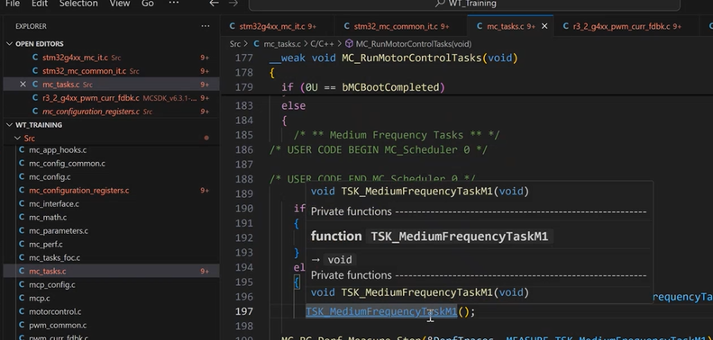
Next, for the auto-generated position control, you’ll need to modify several parts under the current state:
- Alignment
- CAL
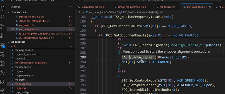
Modify Alignment
The original encoder uses an injected Id current to detect the current angle for alignment.
In this case, we use a predefined initial angle. However, this is specifically for standard encoders, so no additional setup is required.
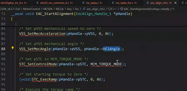
If the selected sensor can store angle information or can be initialized to 0, you can modify this part to set the angle to 0.

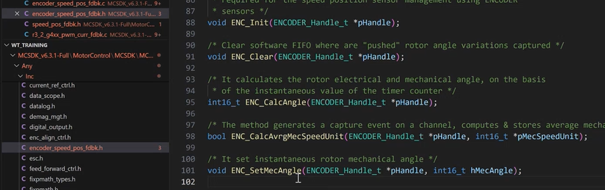
The following summary is based on what’s generated under the Encoder framework.
For other interfaces, just modify the related functions accordingly to reuse the existing architecture.
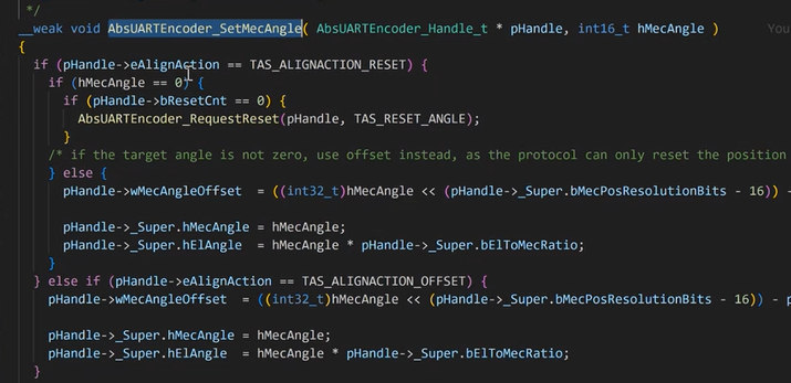
Example (using a Tamagawa encoder)
Here, we write an additional function to replace the original SetMecAngle.
(Note: This function only supports 16-bit data space — if it exceeds that, you’ll need to rewrite the entire logic.)
The concept between the left and right is different:
On the right is the original method using a standard encoder, which applies an Id injection for alignment.
But since the sensor itself outputs the absolute angle, we directly use that angle data for control.
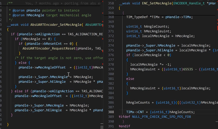
The most important part is angle calculation.
This function continuously updates the value in the medium frequency task.
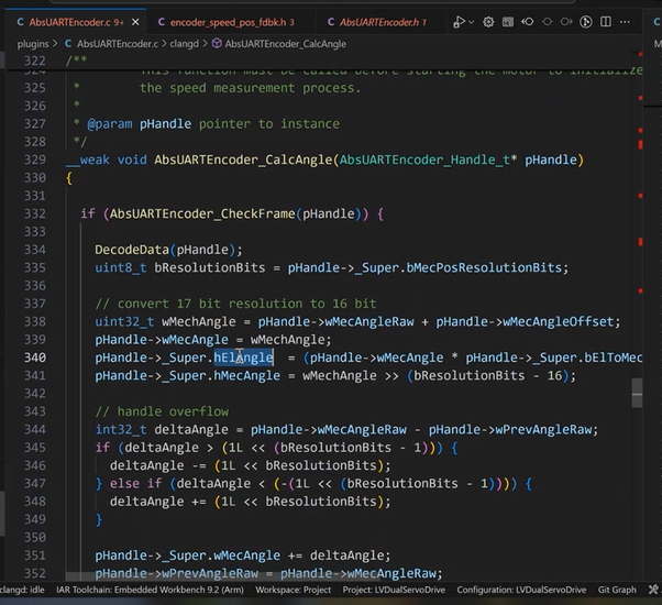
The variable Super.hElAngle must be assigned the most critical angle information from the sensor.
This part needs to be customized under specific conditions.
Other parts can continue to use the original code base.
Limitations
Only 16-bit data can be used here, and the system is based on a 2-loop control architecture.
Additionally, for position trajectory planning, ST uses a standard accumulation method.
As a result, not all applications are suitable — issues like sudden jumps or overshoot often stem from mismatched trajectory planning.