
STM32 Ethernet for H7 Series
Preface
Ethernet functionality exists in high-spec MCU at ST, but there hasn’t been an opportunity to delve into it thoroughly. This time, a customer raised an issue regarding Ethernet connectivity when not plugged in during boot-up; subsequently, it fails to establish a connection when plugged in later. We intend to seize this opportunity to study the usage and detailed specifications of this function.
STM32CubeMX Setting
First, configure the ETH settings for RMII. You can refer to the diagram design or English text settings for this
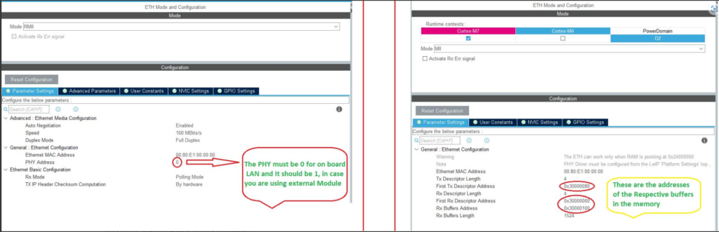
- The LEFT hardware uses the RMII pinout, while the RIGHT one is using MII pinout.
- On the LEFT one we have the option to choose the PHY Address. This should be set to 0, if you are using the on board LAN Port, and it should be 1 in case of the external module.
- On the RIGHT side, the MCU is letting us configure the memory for DMA descriptors, and the Rx Buffer.
- Assuming that each DMA Descriptor takes 32 bits (MAXIMUM Possible), the RX Descriptor and Tx Descriptor have the size of 128 Bytes (32×4).
- The Memory between them is spaced accordingly.
- The Rx Buffer have the size of 1524×4 (Rx DMA Descriptor Length).
- The memories are allocated in the SRAM region, where we can modify the properties later in the MPU.
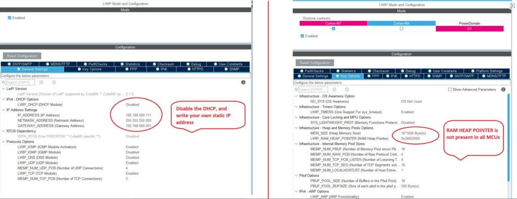
Additionally, enable LWIP with a heap size of 10KB as a unit.
“First, configure the ETH settings for RMII. You can refer to the diagram design or English text settings for this.
Additionally, enable LWIP with a heap size of 10KB as a unit.
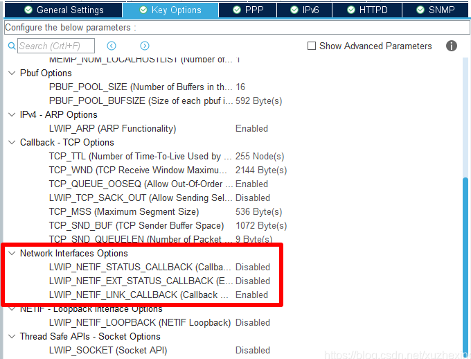
Make sure to select LWIP_NETIF_LINK_CALLBACK, as it’s crucial for the connection status change to trigger the callback function when unplugging or plugging in the network cable
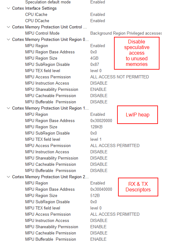
Configuration for Cortex-M7:
LwIP utilizes DMA for message transmission, with corresponding DMA memory defined in SRAM. The SRAM on H7 is divided into several segments, where the high-speed segment is exclusively for CPU use. In simpler terms, this segment allows user-written programs but prohibits DMA usage. Therefore, memory or arrays designated for DMA must avoid this segment. Additionally, when using DMA with LwIP, there are issues related to concurrent access. After avoiding this segment, the CPU cannot utilize cache in a disorderly manner like regular cache usage, as it may lead to severe problems.
(1) LwIP is not permitted to use the CPU’s dedicated high-speed L1 cache (DTCM); it can only utilize the D2 SRAM region.
(2) The CPU can access the cache in a non-sequential manner. To prevent this scenario, the DMA segment of LwIP must be of the device type or strongly-ordered type, ensuring orderliness.
(3) Configure this cache segment through the MPU. One segment allows sharing, buffering, with a length of 256 bytes, designated for TXRX interactive access headers. The other segment does not allow sharing, buffering, or caching, with a length of 32 KB.
Coding (Adding a simple Hello UDP)
Add the following header files at the beginning of main.c:
#include “lwip/udp.h”
#include <string.h>
Write the following code in main.c.
/* USER CODE BEGIN 5 */
const char* message = "Hello UDP message!\n\r";

osDelay(1000);

ip_addr_t PC_IPADDR;
IP_ADDR4(&PC_IPADDR, 192, 168, 1, 1);

struct udp_pcb* my_udp = udp_new();
udp_connect(my_udp, &PC_IPADDR, 55151);
struct pbuf* udp_buffer = NULL;

/* Infinite loop */
for (;;) {
  osDelay(1000);
  /* !! PBUF_RAM is critical for correct operation !! */
  udp_buffer = pbuf_alloc(PBUF_TRANSPORT, strlen(message), PBUF_RAM);

  if (udp_buffer != NULL) {
    memcpy(udp_buffer->payload, message, strlen(message));
    udp_send(my_udp, udp_buffer);
    pbuf_free(udp_buffer);
  }
}
/* USER CODE END 5 */