
VL53L5CX Program Architecture and Porting
Preface
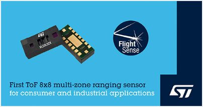
Unlike traditional IR sensors, the VL53L5CX utilizes ST’s latest generation of direct Time-of-Flight (ToF) technology, allowing for absolute distance measurement regardless of target color or reflectivity. It provides accurate ranging up to 400 cm and operates at high speed (60 Hz), making it the fastest multi-zone miniature ToF sensor available on the market.
Hardware Wiring
Here, since the official documentation from ST is quite comprehensive, I will provide an explanation regarding several key points to be aware of.

In the VL53L5 circuitry, the majority of the connections consist of power and ground lines. The main communication components include a 2-pin I2C interface, an INT pin for interrupts, and one GPIO output pin (Ln) for control purposes.
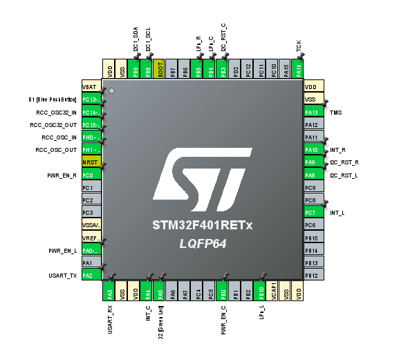
In the official example downloads, you can see that there are quite a few pin definitions. This is because the small boards on both the left and right sides are also included in the configuration.
SW Porting
For the software part, you can start by downloading STSW-IMG023. After the download is complete, the interface will look like the image below.
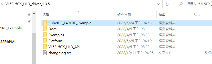
The main components that will be used are VL53L5CX_ULD_API and Platform. The official documentation provides convenience for developers who need to port the software to different platforms. In the Platform folder, the I2C Bus Library for the specific platform can be configured for easy integration.
Undefined
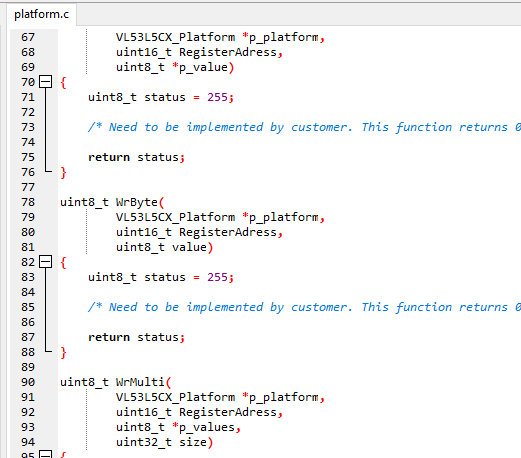
ST sample code(defined)
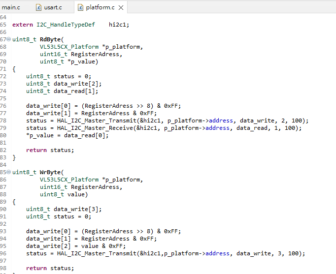
If you are simply porting to different ST MCUs, you can directly take the Platform file from the CubeIDE_F401RE_Example and overwrite it. In this case, you only need to move the corresponding code to different ST MCUs to use it.
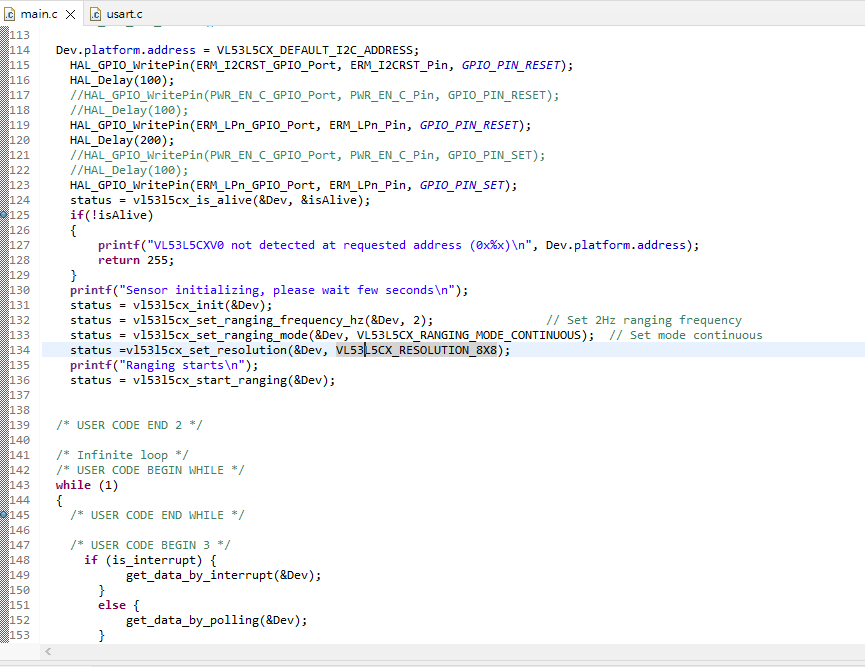
However, you will notice that the resolution is only 4×4. To change it to 8×8 resolution, you can make the necessary modifications in the code.
status =vl53l5cx_set_resolution(&Dev, VL53L5CX_RESOLUTION_8X8);
#define VL53L5CX_RESOLUTION_4X4			((uint8_t) 16U)
#define VL53L5CX_RESOLUTION_8X8			((uint8_t) 64U)
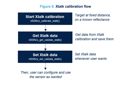
X-Talk CAL
In this example, there is no specific code for handling Offset and X-Talk. The flowchart is as follows:
- Before performing ranging, retrieve the Xtalk value.
- Apply the retrieved Xtalk value as an offset during the ranging process.
	printf("Running Xtalk calibration...\n");

	status = vl53l5cx_calibrate_xtalk(&Dev, 3, 4, 600);
	if(status)
	{
		printf("vl53l5cx_calibrate_xtalk failed, status %u\n", status);
		return status;
	}else
	{
		printf("Xtalk calibration done\n");

		/* Get Xtalk calibration data, in order to use them later */
		status = vl53l5cx_get_caldata_xtalk(&Dev, xtalk_data);

		/* Set Xtalk calibration data */
		status = vl53l5cx_set_caldata_xtalk(&Dev, xtalk_data);
	}