

Adding ADC channels in MCSDK 5.X
Preface
When using MCSDK for motor control, adding additional channels to the existing ADC poses challenges due to considerations such as sampling rates. Attempting to add ADC channels directly using STM32CubeMX may result in system failure. This information is provided to address how to add channels for sampling shunt resistors in a motor control project.
Actual Operation
- Add PB1 ADC1_CH12 as the rotary knob voltage input and PB0 as the control pin output. Generate the project directly using MCSDK.
- Step Two: Open the CubeMx project P NUCLEO IHM001 BullRunning.ioc and add PB1 as ADC_IN12 and PB0 as GPIO_Output.
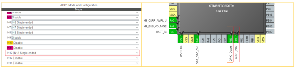
- Step Three: Modify the configuration of the PB0 pin output. In this case, modify it to Pull-up Push-Pull output. Regenerate the project using CubeMx.

Key Steps:
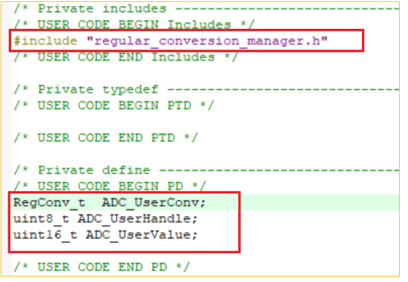
Include the header file in the declaration, and make sure to add the necessary references.
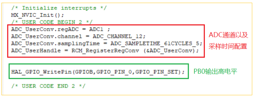
Add initialization procedures for the ADC port configuration and control pin voltage.
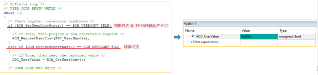
Finally, use built-in functions in conjunction with scheduling.
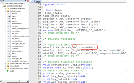
Attention to ADC Channels:
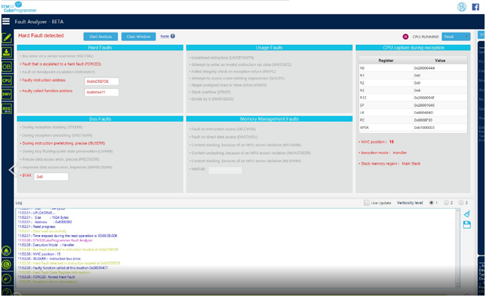
If the channel count is increased without modifying the declaration in the header file, it may lead to a Hard Fault.
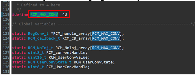
Upon closer examination, it is crucial to modify the RCM_MAX_CONV declaration in addition to changing the channels mentioned above.
Refer
- MCSDK Wiki
- ST MC SDK 5.x 实际使用案例