
Inter-Integrated Circuit(I2C)
Preface
The following article mainly starts from I2C master. If you want to find I2C slave, you can click on the article on the right.
- Hardware: Nucleo-F401RE (STM32F401RE)
- STM32CubeMx software configuration
- IDE: STM32CubeIDE
- STM32F1xx/STM32F4xx HAL library
- I2C: Hardware I2C1.
The physical layer of I2C
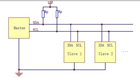
I2C data transmission line => SDA data line: clock Ref:《IIC原理超詳細講解—值得一看》
Ps:The theoretical ideal transmission distance of I2C communication is about 15 meters, but in reality, due to interference and the increase in transmission speed, the actual IC can only support a short distance. It is generally suitable for on-board devices and not suitable for medium to long-distance communication. Things to note for STM32 and hardware:
I2C data transmission

Each bit of I2C data consists of 9 bits If it is sending data, it is 8 bits of data + 1 bit of ACK If it is device address data, it is 8 bits containing 7 bits of device address + 1 bit of direction
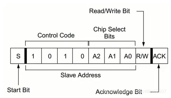
The data is transmitted as a group, so it requires an additional 8-bit sensor or application body to set the receive settings. PS: Due to the transmission signal, which first transmits data in a bi-directional structure, the transmission data sending end includes an address (8-bit) + data (8-bit).
STM32CubeMX I2C Setting

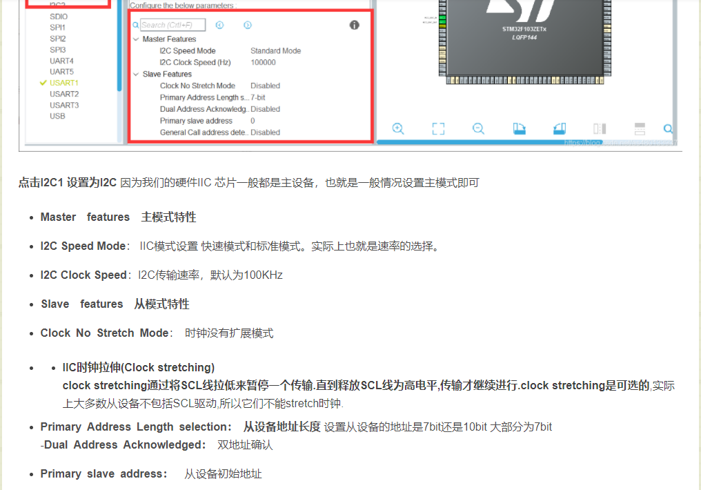
Ref:【STM32】HAL庫STM32CubeMX教程十二—IIC(讀取AT24C02)

PS:It is necessary to avoid sharing the clock as much as possible because it will cause interference between timing signals. If it is necessary to use it, the timing flow procedure must be arranged properly.
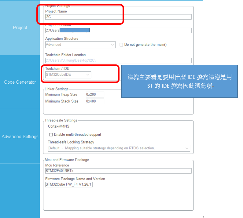
Finally, the code that can be edited in STM32cubeIDE is exported.
I2C Coding
HAL_I2C_Mem_Write

HAL_I2C_Mem_Read

uint8_t read_register(uint8_t Sensor_register)
{
HAL_StatusTypeDef status = HAL_OK;
uint8_t return_value = 0;
status = HAL_I2C_Mem_Read(&hi2c1,Devadress,Sensor_register, I2C_MEMADD_SIZE_8BIT, &return_value, 1, 100);
HAL_Delay(10);
/* Check the communication status */
if(status != HAL_OK)
{
printf("I2C read status error =%#x \n\r",status);
/*
HAL_ERROR = 0x01U,
HAL_BUSY = 0x02U,
HAL_TIMEOUT = 0x03U
*/
}
return return_value;
};
void write_register(uint8_t Sensor_register, uint8_t register_value)
{
HAL_StatusTypeDef status = HAL_OK;
status = HAL_I2C_Mem_Write(&hi2c1, Devadress, Sensor_register, I2C_MEMADD_SIZE_8BIT, ®ister_value,1, 100);
HAL_Delay(10);
/* Check the communication status */
if(status != HAL_OK)
{
printf("I2C write status error =%#x \n\r",status);// Error handling, for example re-initialization of the I2C peripheral
}
}
Additionally, there are four functions that can be used:
- HAL_I2C_Mem_Write_IT
- HAL_I2C_Mem_Read_IT
- HAL_I2C_Mem_Write_DMA
- HAL_I2C_Mem_Read_DMA
- Note that the use of IT should pay attention to whether the Clock flow process will cause tangles.
- Regarding DMA, it is necessary to know the length of the data, and not knowing it may cause program errors.
- HAL_I2C_Master_Transmit/Receive functions are basically used similarly.
I2C transmission fails
- make sure to check if an external resistor has been added.
- The most common mistake in the second part is the wrong address.
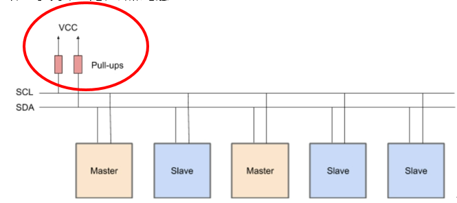
To address the second point, the following program can be used to resolve the issue.
void Scan_i2c_bus_device(void)

{

       int status;

        int i;

        int u8GetDevCnt;

        unsigned char u8data[2];

        printf("Start Scan:\r\n");

        u8GetDevCnt=0;

        for(i=0;i<0xfe;i=i+2)

        {

                status = HAL_I2C_Master_Receive(&hi2c1,(uint16_t)(i), &u8data[0], 1, 10000);

                if(status==HAL_OK)

                {

                                printf("get device on slave addr=0x%x\r\n",i);

                                u8GetDevCnt++;

                }

                HAL_Delay(10);

        }

        printf("Scan get =%d device\r\n",u8GetDevCnt);

        printf("Scan Done!\r\n");

}

Pingback: Pull-up Resistors For I2C Bus - AMS and STM32
Pingback: I2C Slave mode on STM32 Introduction - AMS and STM32