Pull-up Resistors For I2C Bus
Preface
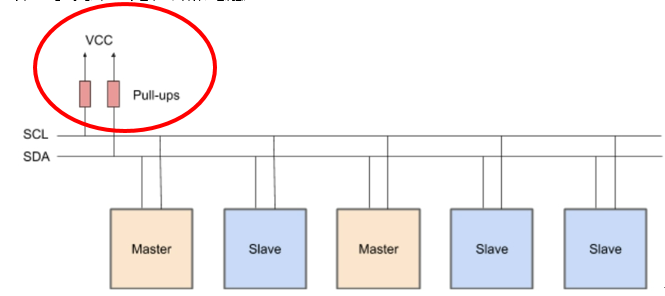
I2C Bus, like SPI, is also a master-slave architecture, but it differs from SPI’s point-to-point or point-to-multipoint structure. It uses a bus structure, allowing multiple masters and multiple slaves to be connected to the bus at the same time. The most important component of the I2C Bus is its pull-up resistors. However, many people have questions about how much resistance should be used and what will happen if they don’t add any or add the wrong value. Here, we will answer these questions one by one and explain the calculation methods, so that you can understand clearly how much resistance is needed for the transmission speed you require.
I2C Bus Structure

In addition to a pair of pull-up resistors Rp, each I2C device may also choose to add a pair of resistors Rs for interference suppression as needed (especially when the SDA and SCL wiring passes through special interference sources). When using I2C, the most troublesome task is to calculate the value of Rp and select a suitable value of Rs for each chip. The value of Rs should be selected according to the actual interference situation of each chip, but the resistance value is generally limited to ≦ Rp/10 (or about 330 Ohms). Because once Rs is not 0, the true Rp(Total) of the chip will become Rp+Rs. Choosing an Rs that is too large will cause Rp(Total) to deviate too much from Rp, affecting the operation of the chip. Rp is generally in the range of 2K~7K Ohms.
- A smaller Rp value results in a waveform that is closer to a square wave, but is more power-consuming
- while a larger Rp value is more power-efficient but results in a waveform that is more susceptible to the effects of charging and discharging of capacitors in the circuit

In-depth exploration of I2C bus structure


- The Output Low circuit can be interpreted as the low-side driver in an I2C device “opposing” the pull-up resistor RP when it wants to pull SCL or SDA to low. The RP resistor impedes the signal from being pulled to high. The ability of the low-side driver to pull the signal to a lower level depends on how much current it can pass through.
- Output Highcircuit is a typical RC voltage charging circuit.
The voltage on the capacitor in this circuit can be expressed using a scary-looking but simple mathematical formula:
V(t)= VCC(1 − e−(t / RC))
The voltage of VCC is fixed, and as the voltage on the capacitor increases, the voltage drop across the resistor decreases, so the current flowing through the resistor to charge the capacitor decreases. As a result, as the voltage on the capacitor increases, the rate of voltage rise slows down.
I2C pull-up Resistor waveform diagram


Pingback: Inter-Integrated Circuit(I2C) - AMS and STM32