I3C (bus) using in STM32H5 series
Preface
MIPI introduced I3C based on I2C, which uses two lines like I2C and supports IBI interrupts and hot swapping. Additionally, it can achieve higher frequencies. Unlike I2C, which uses open-drain outputs on its two pins, and internal ground is unable to output a high level. To achieve a high-level output, an external pull-up resistor is required. However, the resistor impedes current flow, making it time-consuming. I2C can reach a maximum of only 5MB. In contrast, I3C can reach 12.5MB and offers significantly enhanced functionality. Furthermore, it is backward compatible with I2C.
I3C Bus Introduction

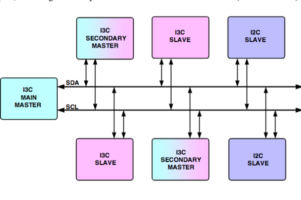
MIPI I3C combines key attributes of traditional I2C and SPI interfaces to provide a unified, high-performance, and extremely low-power solution. The I3C interface uses similar components to I2C, consisting of a single-ended data line (SDA) and a push-pull clock line (SCL). Devices on the SDA line can control the data bus and initiate interrupts. The master controller can adjust the clock frequency of the bus to 12.5MHz via the SCL line. I3C supports various device types, including Main Master (current primary device), Secondary Master (auxiliary primary device), I3C Slave, and I2C Slave.

I2C Vs I3C

Compared to I2C mode, I3C reduces power consumption and provides higher data rates at 12.5MHz.
I3C still supports the ACK confirmation method of I2C, but in some cases, I3C requires using its own method for ACK. The purpose of doing this is to ignore I2C devices on the bus. For example, when dynamically assigning addresses, if you don’t want I2C devices to participate, you can use this method to ignore them. Traditional I2C devices only confirm ACK when SCL is pulled high. If I3C pulls SCL low, I2C devices consider the communication unsuccessful and abandon it.
I3C dedicated VDDIO2 supply pin

The dedicated power supply pin VDDIO2 is reduced to 1.08V. Therefore, all these communication interfaces, including I3C, can operate at a working voltage of 1.2V.
STM32CubeMX – I3C Setting


Bus characteristics
Here we calculate the configuration for two cases.
- The examples using the sensor shield can reach only 3MHz
- The examples using Nucleo boards can reach maximum I3C frequency: 12.5 MHz


Sample code

Here, ST official provides six mode examples for selection. Please confirm according to customer requirements.
  /* Assign dynamic address processus */
  if (HAL_I3C_Ctrl_DynAddrAssign_IT(&hi3c1, I3C_ONLY_ENTDAA) != HAL_OK)
  {
    /* Error_Handler() function is called when error occurs. */
    Error_Handler();
  }

  /*##- Wait for the end of the transfer ############################################*/
  /*  Before starting a new communication transfer, you need to check the current
  state of the peripheral; if it's busy you need to wait for the end of current
  transfer before starting a new one.
  For simplicity reasons, this example is just waiting till the end of the
  transfer, but application may perform other tasks while transfer operation
  is ongoing. */
  while (HAL_I3C_GetState(&hi3c1) != HAL_I3C_STATE_READY)
  {
  }

  /*##- Prepare context buffers process #############################################*/
  /* Prepare context buffer with the different parameters */
  aContextBuffers[I3C_IDX_FRAME_1].CtrlBuf.pBuffer = aControlBuffer;
  aContextBuffers[I3C_IDX_FRAME_1].CtrlBuf.Size    = COUNTOF(aControlBuffer);
  aContextBuffers[I3C_IDX_FRAME_1].RxBuf.pBuffer   = aRxBuffer;
  aContextBuffers[I3C_IDX_FRAME_1].RxBuf.Size      = 14;

  aContextBuffers[I3C_IDX_FRAME_2].CtrlBuf.pBuffer = aControlBuffer;
  aContextBuffers[I3C_IDX_FRAME_2].CtrlBuf.Size    = COUNTOF(aControlBuffer);
  aContextBuffers[I3C_IDX_FRAME_2].TxBuf.pBuffer   = aTxBuffer;
  aContextBuffers[I3C_IDX_FRAME_2].TxBuf.Size      = 4;

  /*##- Add context buffer Get CCC frame in Frame context ###########################*/
  if (HAL_I3C_AddDescToFrame(&hi3c1,
                             aGET_CCCList,
                             NULL,
                             &aContextBuffers[I3C_IDX_FRAME_1],
                             COUNTOF(aGET_CCCList),
                             I3C_DIRECT_WITHOUT_DEFBYTE_RESTART) != HAL_OK)
  {
    /* Error_Handler() function is called when error occurs. */
    Error_Handler();
  }
/*##- Start the reception process #################################################*/
  /* Receive CCC data processus */
  if (HAL_I3C_Ctrl_ReceiveCCC_DMA(&hi3c1, &aContextBuffers[I3C_IDX_FRAME_1]) != HAL_OK)
  {
    /* Error_Handler() function is called when error occurs. */
    Error_Handler();
  }

  /*##- Wait for the end of the transfer ############################################*/
  /*  Before starting a new communication transfer, you need to check the current
  state of the peripheral; if it's busy you need to wait for the end of current
  transfer before starting a new one.
  For simplicity reasons, this example is just waiting till the end of the
  transfer, but application may perform other tasks while transfer operation
  is ongoing. */
  while (HAL_I3C_GetState(&hi3c1) != HAL_I3C_STATE_READY)
  {
  }

  /*##- Monitor the different value retrieve during CCC get #########################*/
  /*  At the end, of transfer, the application have retrieve all the data of
  the frame in an unique buffer, which must be unfill to retrieve the associated
  value for each get CCC command. */
  /* Display through external Terminal IO the Get CCC associated value received */
  DisplayCCCValue(aGET_CCCList, &aCommandCode[0], &aRxBuffer[0], COUNTOF(aGET_CCCList));

  /*##- Add context buffer Set CCC frame in Frame context ###########################*/
  if (HAL_I3C_AddDescToFrame(&hi3c1,
                             aSET_CCCList,
                             NULL,
                             &aContextBuffers[I3C_IDX_FRAME_2],
                             COUNTOF(aSET_CCCList),
                             I3C_DIRECT_WITHOUT_DEFBYTE_RESTART) != HAL_OK)
  {
    /* Error_Handler() function is called when error occurs. */
    Error_Handler();
  }
