

Low Power PWM(Timer)
Preface
With the increasing demand for low-power products, ST has introduced MCUs and corresponding pins for low-power applications. The L series in ST MCU is a dedicated MCU for low power, and some other MCUs also have low-power pins, such as the F7, H7, G0, G4, and WB series. This chapter will provide a detailed explanation and usage of the LPTIM pin for switching oscillation sources
LPTIM Function
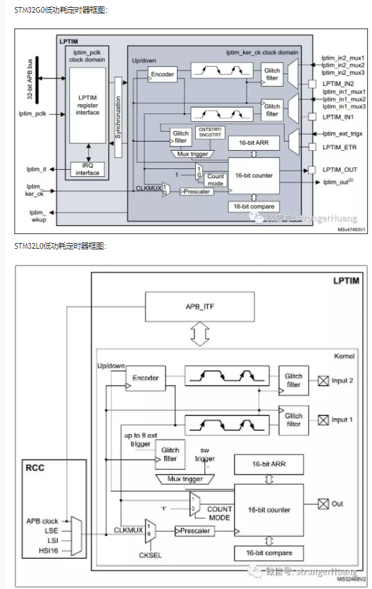
LPTIM: Low-Power Timer, a 16-bit timer designed for low-power applications. The main difference between LPTIM and regular TIM is that LPTIM can run in all power modes, even in standby mode, and can operate without an internal clock source. As shown in the diagram below, LPTIM on the L0 series is different from that on the G0 series, so the configuration of LPTIM may vary across different series and needs to be confirmed (the WB series shares the same LPTIM configuration as the G0 series).

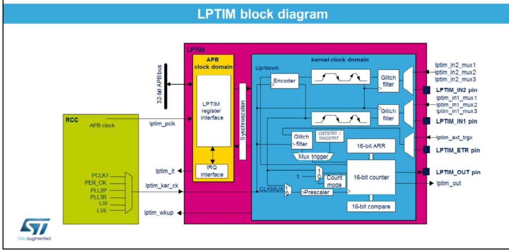
NOTE:The CLKMUX selection corresponds to bit 0 (CKSEL) of the CFGR register, which controls the selection of the internal clock source (APB or any other internal oscillator such as LSE, LSI, and HSI), or an external clock source via LPTIM external input.
LPTIM characteristic
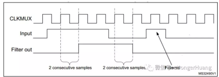
Internal clocks: LSE, LSI, HSI or APB External clocks for LPTIM input (pulse counter can be used in the absence of LP oscillator) The LPTIM also has a glitch filter (as shown in the figure below).
LPTIM_ClockConfigTypeDef Define
typedef struct
{
  uint32_t Source;
  uint32_t Prescaler;
}LPTIM_ClockConfigTypeDef;
Sources can be selected as follows:
- #define LPTIM_CLOCKSOURCE_APBCLOCK_LPOSC ((uint32_t)0x00U)
- #define LPTIM_CLOCKSOURCE_ULPTIM LPTIM_CFGR_CKSEL
The first one indicates that LPTIM uses an internal clock (APB or LSE, LSI, and HSI, etc.).
The second one indicates that LPTIM is provided with a clock via the LPTIM external Input1 from an external clock source.
Timer (GPIO、Clock、interrupt)
HAL_LPTIM_Init this function include HAL_LPTIM_MspInit
__weak void HAL_LPTIM_MspInit(LPTIM_HandleTypeDef *hlptim)
{
  /* Prevent unused argument(s) compilation warning */
  UNUSED(hlptim);

  /* NOTE : This function Should not be modified, when the callback is needed,
            the HAL_LPTIM_MspInit could be implemented in the user file
   */
}
PS:In addition to basic settings, GPIO, clock, and interrupts need to be configured for complete use. The following is an example of configuring LPTIM1 to use PD13 as PWM.
void HAL_TIM_PWM_MspInit(TIM_HandleTypeDef *htim)
{
GPIO_InitTypeDef     GPIO_InitStruct;

  /* 使用LPTIM Clock */
  __HAL_RCC_LPTIM1_CLK_ENABLE();

  /* 使用GPIO  Enable GPIO PORT */
  __HAL_RCC_GPIOD_CLK_ENABLE();

  /* 配置PD13 */
  GPIO_InitStruct.Pin = GPIO_PIN_13;
  GPIO_InitStruct.Mode = GPIO_MODE_AF_PP;
  GPIO_InitStruct.Pull = GPIO_PULLUP;
  GPIO_InitStruct.Speed = GPIO_SPEED_FREQ_MEDIUM;
  GPIO_InitStruct.Alternate = GPIO_AF1_LPTIM1;
  HAL_GPIO_Init(GPIOD, &GPIO_InitStruct);
}
Sum
- Initialization is done through the function HAL_LPTIM_Init().
- The underlying configuration of the low-power timer is implemented through the function HAL_LPTIM_MspInit().
- Select one of the six operating modes supported by the low-power timer:
- PWM mode: use HAL_LPTIM_PWM_Start() or HAL_LPTIM_PWM_Start_IT()
- One-pulse mode: in this mode, the output can switch between high and low voltage when a condition is met, use HAL_LPTIM_SetOnce_Start() or HAL_LPTIM_SetOnce_Start_IT()
- Encoder mode: HAL_LPTIM_Encoder_Start() or HAL_LPTIM_Encoder_Start_IT() (!!note that not all LPTIMs support this mode!!)
- Timeout mode: HAL_LPTIM_TimeOut_Start() or HAL_LPTIM_TimeOut_Start_IT()
- Counter mode: HAL_LPTIM_Counter_Start() or HAL_LPTIM_Counter_Start_IT()
- Stop any mode: users can stop any mode by calling the corresponding API: HAL_LPTIM_Xxx_Stop or HAL_LPTIM_Xxx_Stop_IT() (if this mode has already been started in interrupt mode).”