Shunt resistor
Preface
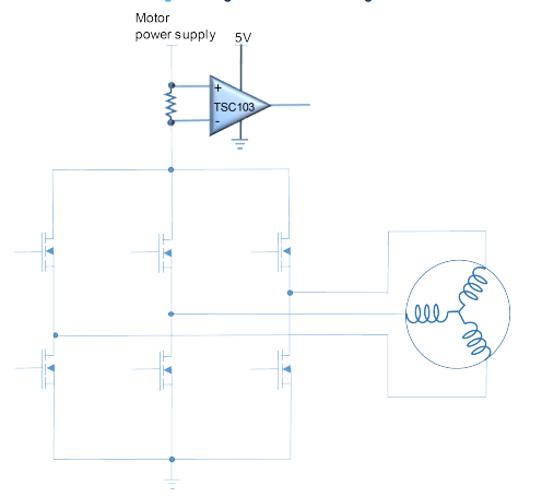
A current sensing resistor (shunt resistor) is usually placed on one of the three-phase lines. The voltage drop across this resistor can be amplified by an operational amplifier (op-amp), and then received by a sensor and converted into a digital signal. In this way, we can detect the current of the motor in the driver and stop or adjust the operation of the motor when necessary, thereby protecting the driver and motor and extending their service life
Spindle circuit
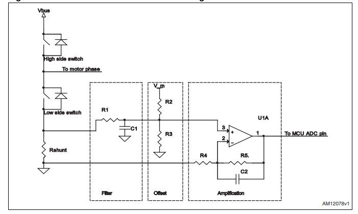
The diagram below shows that it is mainly divided into three parts
- Fliter
- Offset
- Amplification
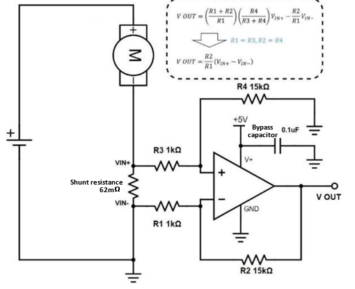
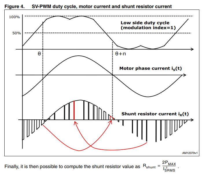
The higher the resistance value, the greater the voltage drop for a given current, thus reducing the available useful signal. On the other hand, the power dissipation through the shunt resistor increases with the resistance value, so the resistance value depends mainly on what percentage of the maximum acceptable power dissipation (PMAX) is.
Layout of shunt resistor, you could refer as below
Although minimizing the parasitic inductance of the traces (which is proportional to their length and inversely proportional to their width) can reduce oscillations, some filtering is always necessary to clean up the feedback signal and potentially make it reach steady-state faster, thus expanding the time range during which the downstream microcontroller unit can read the current feedback signal. On the other hand, the filter cannot be too strong, because as mentioned earlier, the current only flows through the shunt resistor when the low-side switch is on.
Layout suggestion
- With reference to Figure 3, and for each of the shunt resistors, directly connect R1 andR4 terminals to shunt resistor terminals. Furthermore, these two should go close toeach other from resistor to op amp to minimize the introduction of differential electricalnoise.
- Keep traces between resistors and op amps far away from high voltage traces (even ifon different PCB layers). This would help avoid capacitive couplings.
- Try to place operational amplifiers and related components as close as possible toshunt resistors.
Four type as below
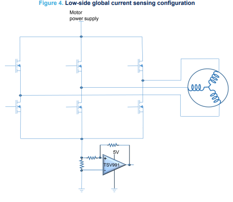
Low-side global current sensing
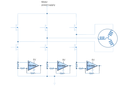
Low-side current sensing in each leg of the current driver
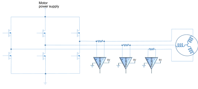
Inline phase current
High-side current sensing