

Low Power Modes For STM32L4
Preface
Nowadays, MCUs are required to be power-efficient. ST has introduced the L series and the latest U5 series of MCUs for power-saving purposes. This chapter will mainly introduce the operations under various power-saving modes, and provide an example program using the Sleep mode. It will also highlight important points and precautions for customers who encounter issues. The L4 series MCU will also be covered in this chapter.
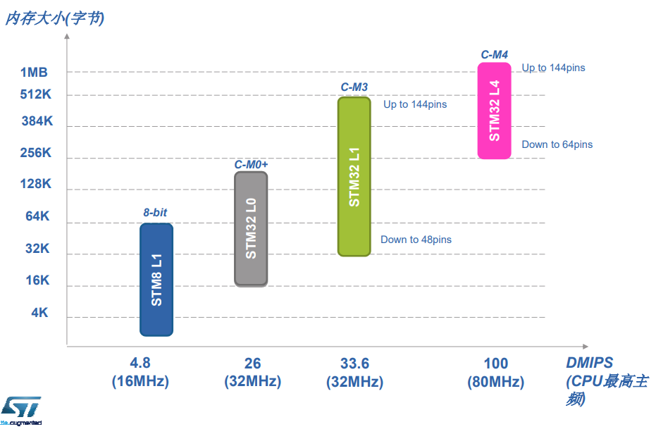
STM32L series core
Here, we can see that the L4 core processor has reached the Core-M4
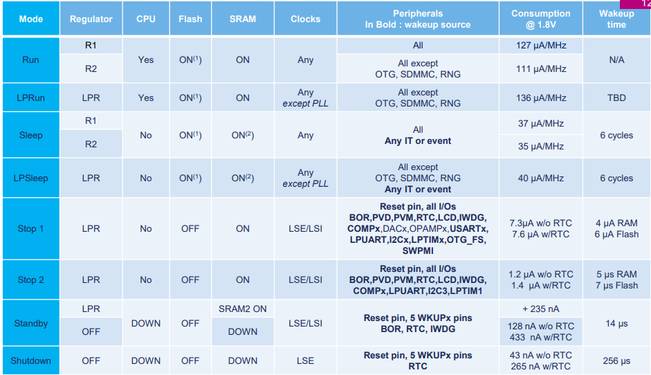
Low-power modes summary
corresponding computing performance has greatly increased. In this section, we will mainly introduce the commonly used L4 in the L series, and the following table shows which parts of L4 will enter sleep mode in each state and which can be used (power consumption can be achieved, but the control conditions and precautions are more stringent).”
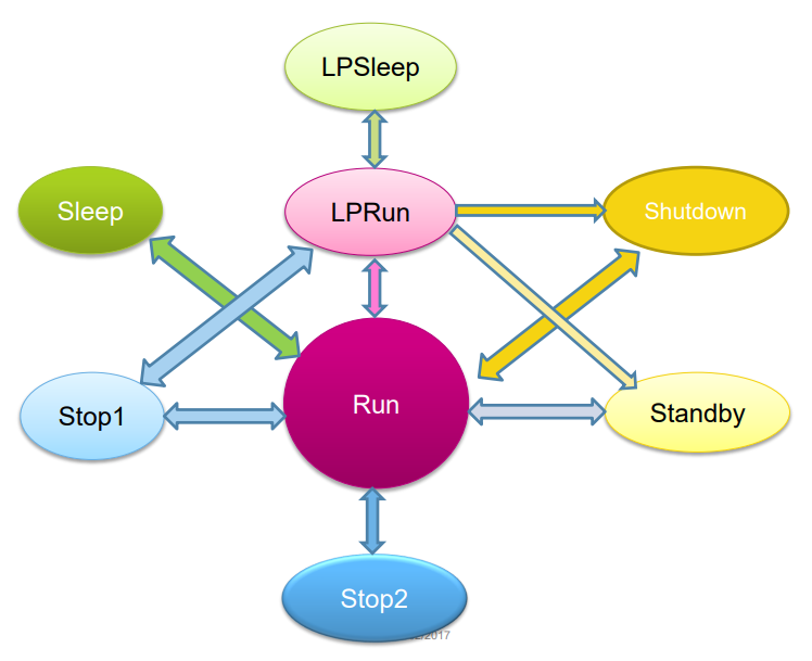
Low-power modes transitions
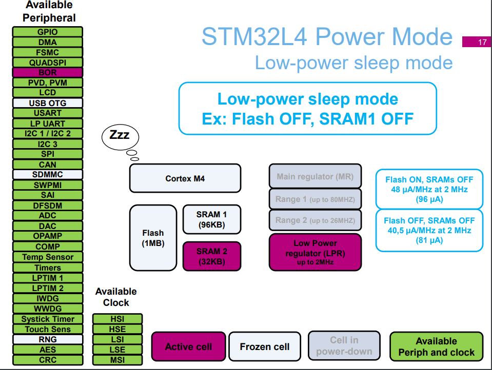
STM32L4 Sleep mode Implementation
Having gone through the above introduction, we now have a deeper understanding of the Low Power series. Here, we will implement the Low Pow Sleep mode.
Hardware considerations:
- GPIO leakage issues
- Soldering issues
GPIO leakage issues
After entering low power mode, there is charge flow in the GPIO ports of STM32 due to pressure difference. Therefore, before entering low power mode, pull all GPIO pins to the same level as the outside world. We can refer to the following example to understand better:
Example 1: After connecting the LCD module to the MCU, the power consumption of the whole board is more than 800uA instead of 1.6uA in STOP mode (the code is the same).
Problem Analysis
- After removing the LCD module, the power consumption drops to 500uA.
- All modules are controlled by GPIO pins.
Solution: Before entering STOP mode, pull all pins to HIGH (same level as LCD voltage).
Soldering issues
In fact, this problem is similar to the GPIO issue, and poor soldering contact can also cause current leakage.
Coding
To achieve extremely low power consumption, it is essential to turn off necessary clock sources and GPIO pins
void SystemClock_Decrease(void)
{
  RCC_ClkInitTypeDef RCC_ClkInitStruct = {0};
  RCC_OscInitTypeDef RCC_OscInitStruct = {0};

  /* MSI is enabled in range 0 (100Khz) */
  RCC_OscInitStruct.OscillatorType = RCC_OSCILLATORTYPE_MSI;
  RCC_OscInitStruct.MSIState = RCC_MSI_ON;
  RCC_OscInitStruct.MSIClockRange = RCC_MSIRANGE_0;//100khz
  RCC_OscInitStruct.MSICalibrationValue = RCC_MSICALIBRATION_DEFAULT;
  RCC_OscInitStruct.PLL.PLLState = RCC_PLL_NONE;
  if(HAL_RCC_OscConfig(&RCC_OscInitStruct) != HAL_OK)
  {
    /* Initialization Error */
    Error_Handler();
  }
  /* Select MSI as system clock source and keep HCLK, PCLK1 and PCLK2 clocks dividers as before */
  RCC_ClkInitStruct.ClockType = RCC_CLOCKTYPE_SYSCLK;
  RCC_ClkInitStruct.SYSCLKSource = RCC_SYSCLKSOURCE_MSI;
  if(HAL_RCC_ClockConfig(&RCC_ClkInitStruct, FLASH_LATENCY_0) != HAL_OK)
  {
    /* Initialization Error */
    Error_Handler();
  }
  /* Disable HSI to reduce power consumption since MSI is used from that point */
  __HAL_RCC_HSI_DISABLE();
}
static void SystemPower_Config(void)
{
  GPIO_InitTypeDef GPIO_InitStructure;

  /* Enable GPIOs clock */
  __HAL_RCC_GPIOA_CLK_ENABLE();
  __HAL_RCC_GPIOB_CLK_ENABLE();
  __HAL_RCC_GPIOC_CLK_ENABLE();
  __HAL_RCC_GPIOD_CLK_ENABLE();
  __HAL_RCC_GPIOH_CLK_ENABLE();
  __HAL_RCC_GPIOE_CLK_ENABLE();
  __HAL_RCC_GPIOF_CLK_ENABLE();
  __HAL_RCC_GPIOG_CLK_ENABLE();

  /* Configure all GPIO port pins in Analog Input mode (floating input trigger OFF) */
  GPIO_InitStructure.Pin = GPIO_PIN_All;
  GPIO_InitStructure.Mode = GPIO_MODE_ANALOG;
  GPIO_InitStructure.Pull = GPIO_NOPULL;
  HAL_GPIO_Init(GPIOA, &GPIO_InitStructure);
  HAL_GPIO_Init(GPIOB, &GPIO_InitStructure);
  HAL_GPIO_Init(GPIOC, &GPIO_InitStructure);
  HAL_GPIO_Init(GPIOD, &GPIO_InitStructure);
  HAL_GPIO_Init(GPIOH, &GPIO_InitStructure);
  HAL_GPIO_Init(GPIOE, &GPIO_InitStructure);
  HAL_GPIO_Init(GPIOF, &GPIO_InitStructure);
  HAL_GPIO_Init(GPIOG, &GPIO_InitStructure);

  /* Disable GPIOs clock */
  __HAL_RCC_GPIOA_CLK_DISABLE();
  __HAL_RCC_GPIOB_CLK_DISABLE();
  __HAL_RCC_GPIOC_CLK_DISABLE();
  __HAL_RCC_GPIOD_CLK_DISABLE();
  __HAL_RCC_GPIOH_CLK_DISABLE();
  __HAL_RCC_GPIOE_CLK_DISABLE();
  __HAL_RCC_GPIOF_CLK_DISABLE();
  __HAL_RCC_GPIOG_CLK_DISABLE();
}
主程式如下
int main(void)
{
  /* USER CODE BEGIN 1 */

  /* USER CODE END 1 */

  /* MCU Configuration--------------------------------------------------------*/

  /* Reset of all peripherals, Initializes the Flash interface and the Systick. */
  HAL_Init();

  /* USER CODE BEGIN Init */

  /* USER CODE END Init */

  /* Configure the system clock */
  SystemClock_Config();

  /* USER CODE BEGIN SysInit */

  /* USER CODE END SysInit */

  /* Initialize all configured peripherals */
  MX_GPIO_Init();
  MX_USART2_UART_Init();
  /* USER CODE BEGIN 2 */
  BSP_LED_Init(LED2);
  printf("start\n\r");
  /* Disable Prefetch Buffer */
   __HAL_FLASH_PREFETCH_BUFFER_DISABLE();

   /* Enable Power Clock */
   __HAL_RCC_PWR_CLK_ENABLE();

   /* Enable Flash power down mode during Sleep mode     */
   /* (uncomment this line if power consumption figures  */
   /*  must be measured with Flash still on in Low Power */
   /*  Sleep mode)                                       */
   __HAL_FLASH_SLEEP_POWERDOWN_ENABLE();

   /* Reset all RCC Sleep and Stop modes register to */
   /* improve power consumption                      */
   RCC->AHB1SMENR  = 0x0;
   RCC->AHB2SMENR  = 0x0;
   RCC->AHB3SMENR  = 0x0;

   RCC->APB1SMENR1 = 0x0;
   RCC->APB1SMENR2 = 0x0;
   RCC->APB2SMENR  = 0x0;
  /* USER CODE END 2 */

  /* Infinite loop */
  /* USER CODE BEGIN WHILE */
  while (1)
  {
    /* USER CODE END WHILE */
	  HAL_Delay(5000);

	  if (BSP_PB_GetState(BUTTON_USER) == SET)
	  {
	  SystemPower_Config();
	  BSP_PB_Init(BUTTON_USER, BUTTON_MODE_EXTI);
	  SystemClock_Decrease();
	  HAL_SuspendTick();
	  HAL_PWR_EnterSLEEPMode(PWR_LOWPOWERREGULATOR_ON, PWR_SLEEPENTRY_WFI);
	  HAL_PWREx_DisableLowPowerRunMode();
	  SystemClock_Config();
	  BSP_LED_Init(LED2);
	  HAL_ResumeTick();
	  }
    /* USER CODE BEGIN 3 */
  }
  /* USER CODE END 3 */
}