Hall sensors placement angle
Preface
When using the ST FOC motor control library with Hall signals as the position feedback, synchronous electrical angle data must be input based on the characteristics of the motor being used. This data synchronizes the electrical angle with the Hall signal at each signal change. If the angle deviation is large, it may affect the control effect and lead to efficiency loss or motor oscillation. Therefore, initial testing is necessary. This article provides detailed instructions on the testing precautions and methods.
Test Preparation
If there is no virtual midpoint connection in the motor, three resistors of the same value need to be connected to the three-phase wiring of the motor, and the other end of the resistors should be connected together as a virtual midpoint.
Connect the Hall signal to 5V power supply and connect a pull-up resistor to H1. Connect to an oscilloscope, rotate the motor, and test the reverse electromotive force signal and the Hall signal.

Waveform testing and calculation results
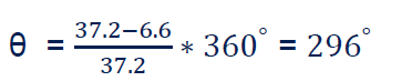
Measure the time of one electrical cycle, which corresponds to 360 degrees

Test the time from the highest point of the reverse electromotive force of Motor Phase A to H1. In the figure, the pink waveform represents the reverse electromotive force of Motor Phase A, and the red digital port D0 represents the H1 sign

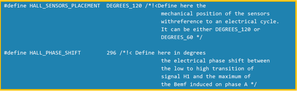
The synchronous electrical angle of the motor
Add the synchronous angle to the code.
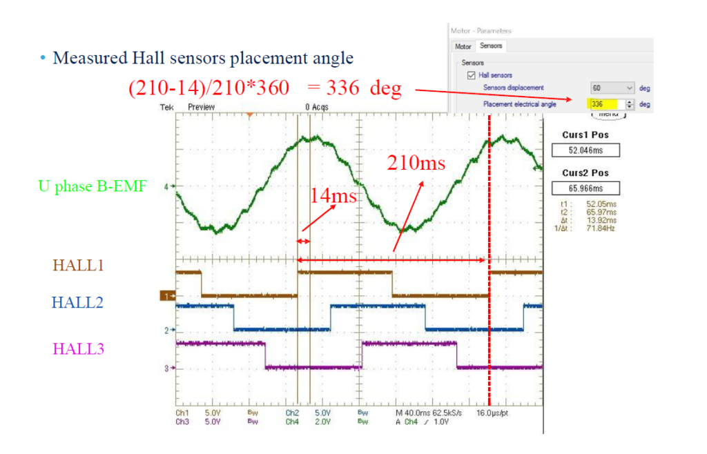
If using Workbench, add it to the motor parameters as shown in the figure:

If directly written into the program, write the data into the PMSM motor parameters.h file parameters