

STM32 DMA Introduction
Basic introduction to DMA
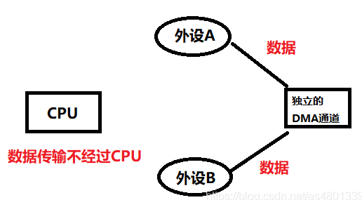
DMA, short for Direct Memory Access, allows data to be transferred from one address space to another without CPU intervention. It provides high-speed data transfer between external memory or between registers without the need for CPU involvement. DMA transfers can quickly move data without CPU intervention.
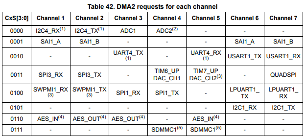
DMA mapping
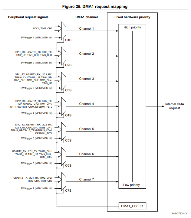
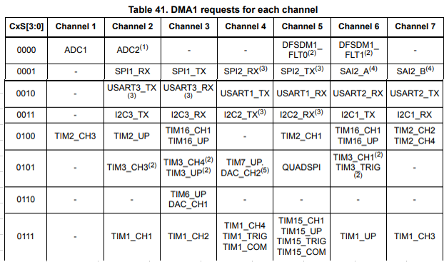
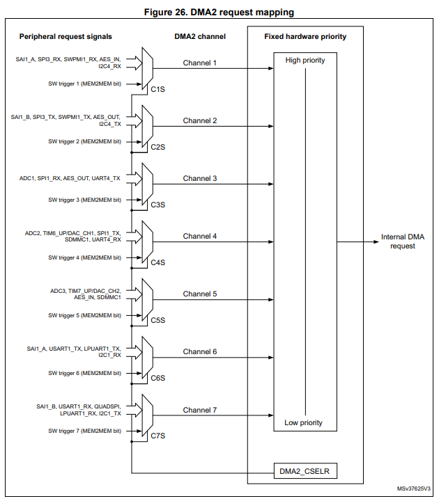
Since the WB series is based on the L4 series with a Core-M0, we can directly refer to the mapping chart of the L4 series, which shows which channels support what types of data access.
DMA Transactions
DMA transfer transactions consist of a series of data transfer sequences of a given number. The number of transfers can be set by software and can be 8-bit, 16-bit, or 32-bit. Each DMA transfer involves three operations
- Data is loaded into an external data buffer or memory unit via the DMA_SxPAR or DMA_SxM0AR registers.
- The loaded data is stored into an external data buffer or memory unit via the DMA_SxPAR or DMA_SxM0AR registers.
- The DMA_SxNDTR counter is decremented after the data storage operation, and it contains the number of transactions that still need to be performed.
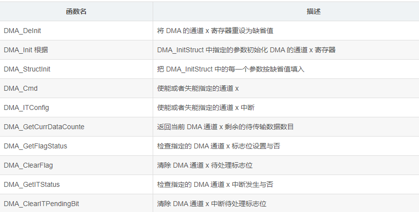
DMA Function
The table is for the F10X series and can be referenced for the WB series in the Description of STM32WB HAL and low-layer drivers (Page 181: DMA Firmware driver API description), which has some modifications to certain functions.
DMA Using
- Polling mode Polling mode allows DMA transfers to be performed without enabling DMA interrupts. By using the DMA_GetFlagStatus function to determine whether the transfer is complete, half complete, or an error occurred, the DMA channel can be disabled. After completing the corresponding operations, the flag bit is cleared, and then the DMA channel is enabled by using the DMA_SetCurrDataCounter function to reset the buffer size.
- Interrupt mode DMA interrupts are generally used for fixed-length data transfers, such as transfer complete interrupt. When a DMA transfer complete interrupt is generated, the interrupt flag bit and transfer complete flag bit are cleared. Then the DMA channel is disabled, and the data is processed. The DMA buffer size can be reset (optional), and then the DMA channel is enabled.
- Variable-length data transfer For variable-length data transfer, such as using a UART, the transfer completion can be determined through the UART idle interrupt (the transfer buffer size must be greater than the transferred data size). The length of the data can be calculated by using the DMA_GetCurrDataCounter function. After that, the DMA channel is disabled, and the buffer size is reset, and then the DMA channel is enabled.
- Double buffer mode Double buffer mode involves setting up two buffers and a flag (used to distinguish which buffer is being used). After each transfer is completed, the buffer address is updated by reconfiguring DMA_MemoryBaseAddr to point to the next buffer. The data from the next transfer will be saved in the new buffer. A custom flag can be used to determine and switch between the buffers.