STM32 Watchdog Introduction
Preface
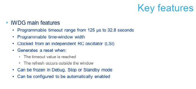
- IWDG is best suited for applications that require a watchdog to work completely independently outside the main program and have lower requirements for time accuracy.
- WWDG is best suited for applications that require the watchdog to function within a precise timing window.
IWDG (Independent watchdog) is used to detect and solve faults caused by software errors. When the counter reaches a given timeout value, it triggers an interrupt or generates a system reset. The independent watchdog clock is its dedicated low-speed clock (LSI), so it can continue to work even if the main clock has problems. The window watchdog clock is obtained through the APB1 clock divider, and it detects abnormal delays or premature operations of the application program through a configurable time window.
The Window watchdog is typically used to monitor software faults caused by external interference or unpredictable logical conditions that cause the application to deviate from its normal execution sequence. Unless the value of the decrementing counter is refreshed before T6 bit becomes 0, the watchdog circuit will generate an MCU reset when the preset time period is reached. An MCU reset will also occur if the 7-bit decrement counter value in the control register is refreshed before the decrementing counter reaches the value in the window register. This means that the counter must be refreshed within the defined time window.
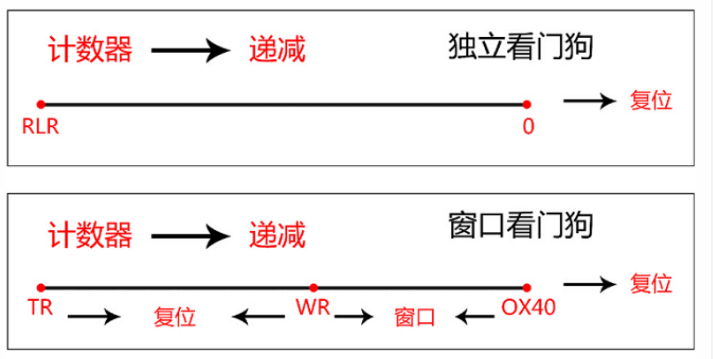
Description of Independent Watchdog Functionality
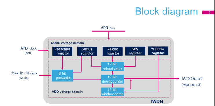
A programmable 8-bit prescaler is used to divide the LSI oscillator frequency.
Note:Writing 0XCCCC to (IWDG_KR) activates the independent watchdog, and the counter starts to decrement from the reset value 0XFFF. When the counter value reaches 0, a reset signal (independent watchdog reset) is generated. Whenever 0XAAAA is written to the keyword register, the value of IWDG_RLR is reloaded into the counter, avoiding watchdog reset.
Register Access Protection
The IWDG_PR and IWDG_RLR registers have write access protection. To modify these registers, the code must first write 0x5555 to the IWDG_KR register. Writing any other value would break this sequence, thus re-enabling the register access protection. This means that a firmware update operation (i.e., writing 0xAAAA) would also activate the write protection. The status register indicates whether the prescaler value and the decrement counter are being updated.
Debug Mode
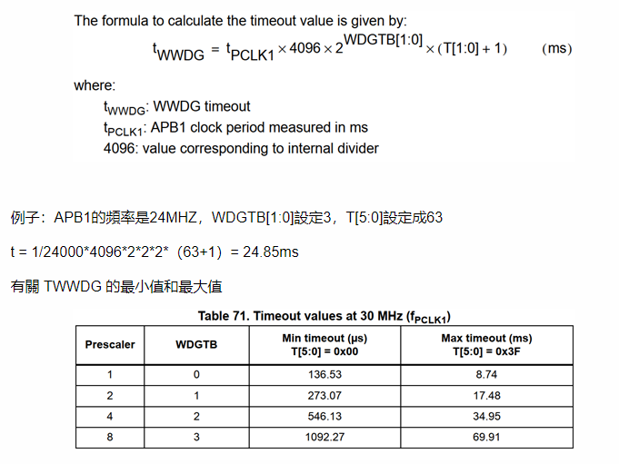
When the microcontroller enters debug mode (Cortex™-M3 core halted), the IWDG counter will either continue to operate normally or stop based on the configuration of the DBG_IWDG_STOP bit in the DBG module. The following figure shows the minimum and maximum IWDG timeout periods for different prescaler values of the LSI

Description of Window Watchdog function
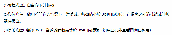
If the Window Watchdog is enabled (WDGA bit of WWDG_CR register is set to 1), the 7-bit down-counter rolls over from 0x40 to 0x3F (T6 has been cleared), which will cause a reset. If the software overloads the counter, a reset will occur when the counter value exceeds the value stored in the window.

The application must write to the WWDG_CR register during normal operation to orchestrate an MCU reset. This operation must occur when the counter value is less than the value stored in the window register. The value stored in the window register is stored in the WWDG_CR register and must be between 0xFF and 0xC0.
Note: (Advanced Features of Watchdog Interrupt) If specific safety operations or data logging must be performed before generating an actual reset, the Early Wakeup Interrupt (EWI) can be used. Enabling the EWI interrupt is done by setting the EWI bit in the WWDG_CFR register. An EWI interrupt will be generated when the decrementing counter reaches the value of 0x40. Before resetting the device, the corresponding Interrupt Service Routine (ISR) can be used to trigger specific operations (such as communication or data logging). In some applications, EWI interrupts can be used to manage software system checks and/or system recovery/degradation without generating a WWDG reset. In this case, the corresponding ISR can be used to overload the WWDG counter to avoid a WWDG reset, and then trigger the required operation. The EWI interrupt can be cleared by writing 0 to the EWIF bit in the WWDG_SR register.
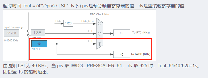
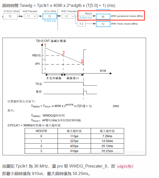
How to set watchdog timeout
Debug mode
When the microcontroller enters debug mode (Cortex™-M3 core stops), the WWDG counter will continue to work or stop according to the DBG_WWDG_STOP configuration bit in the DBG module.”
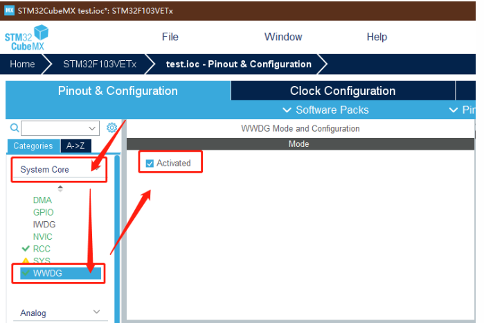
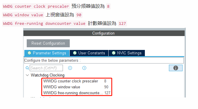
STM32CubeMX WWDG Setting
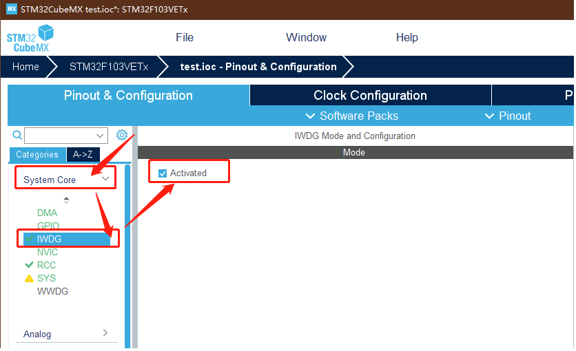
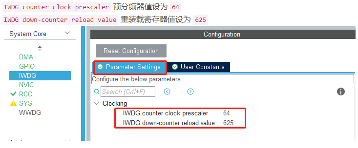
STM32CubeMX IWDG Setting