

STM32Cude Tool
Preface
In the previous section, we introduced STM32CubeMX, and in this chapter, we will delve into the program compilation with CubeIDE and burning methods with CubeProgram.
STM32CubeIDE
The online resources mainly focus on MDK and CubeIDE. Here we will mainly introduce the CubeIDE. The first step is to introduce the basic interface as shown in the figure below.
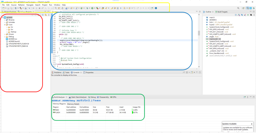
- Yellow box: Setting column list, which mainly includes the Debug symbol of the beetle and the Burn button of the playback button that is most commonly used.
- Red box: indicates the type of project that has been initiated.
- Blue box: programming editor window
- Green box: After programming is burned in, you can check the usage rate of RAM and other resources, but not for the stack/heap.
Debug mode
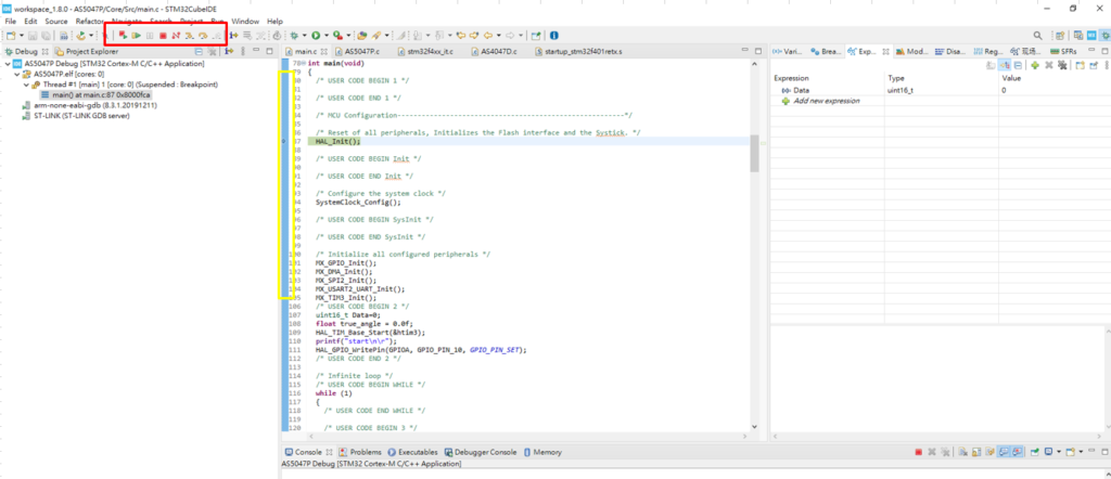
When entering Debug mode here, you can see that it is divided into three major sections. On the far left, you can see where the program is currently running in detail. On the right, the “eyeglass” EXP position allows you to monitor the status of internal variables in real time. The middle program section is the currently running function area.
The red box area is mainly used for executing the next step of the program or stopping Debug mode, while the yellow area is the same as setting breakpoints in a normal program.
STM32CubeProgram
The current main use of CubeProgram is for burning and option byte setting. It is a relatively convenient software for configuring the flash and so on. The basic operation interface can be seen below.
Note that the general public version provided by ST supports ST-LINK. If you want to use SPI and I2C for burning, you need to use ST’s official ST-Link V3.
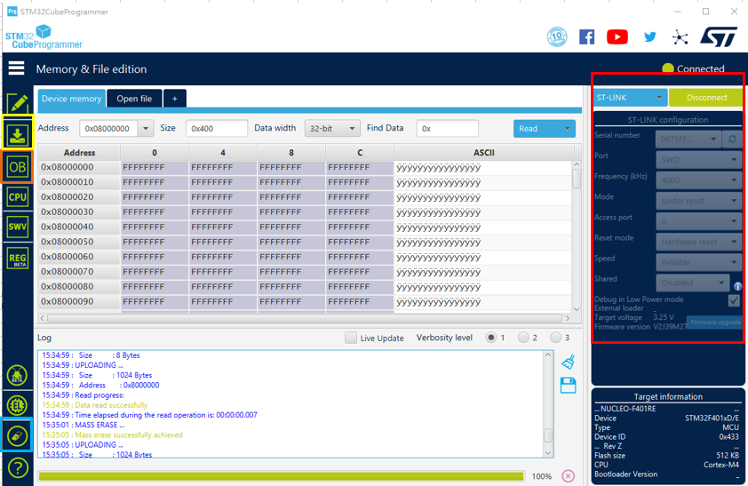
- Red box: Connection or burning selection method selected
- Yellow box: Burning settings and actual burning usage
- Orange box (OB): Option byte setting
- Blue box: Erase all memory positions
The middle section displays the Flash position and data, and double-clicking the left mouse button quickly allows direct modification of the internal values.
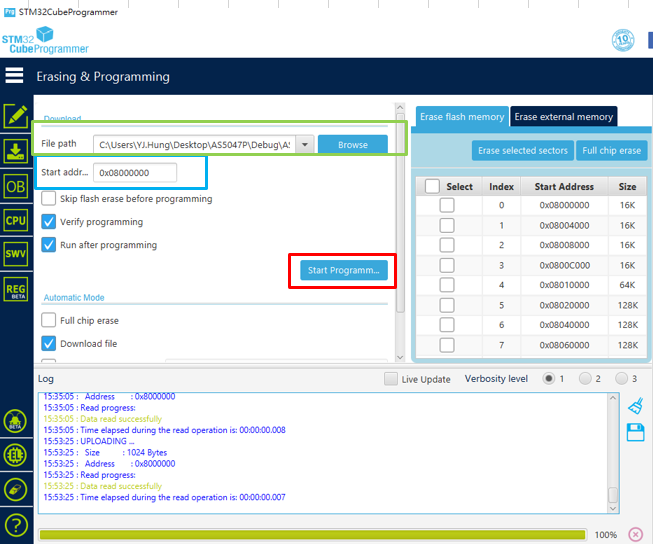
In the burning section, as shown in the above figure, there are mainly three blocks to be set.
- Green box: First, select the file to be burned. Here you can choose either a Bin file or a Hex file.
- Blue box: Set the starting position for burning. (This position is usually not set unless you are using dual banks or cutting the application into segments.)
- Red box: Start burning
In the following figure, we can see the Option Bytes setting. (The biggest difference between STM32 and STM8 is that Option Bytes will no longer generate additional files, so they will be burned in batch using command line form.)
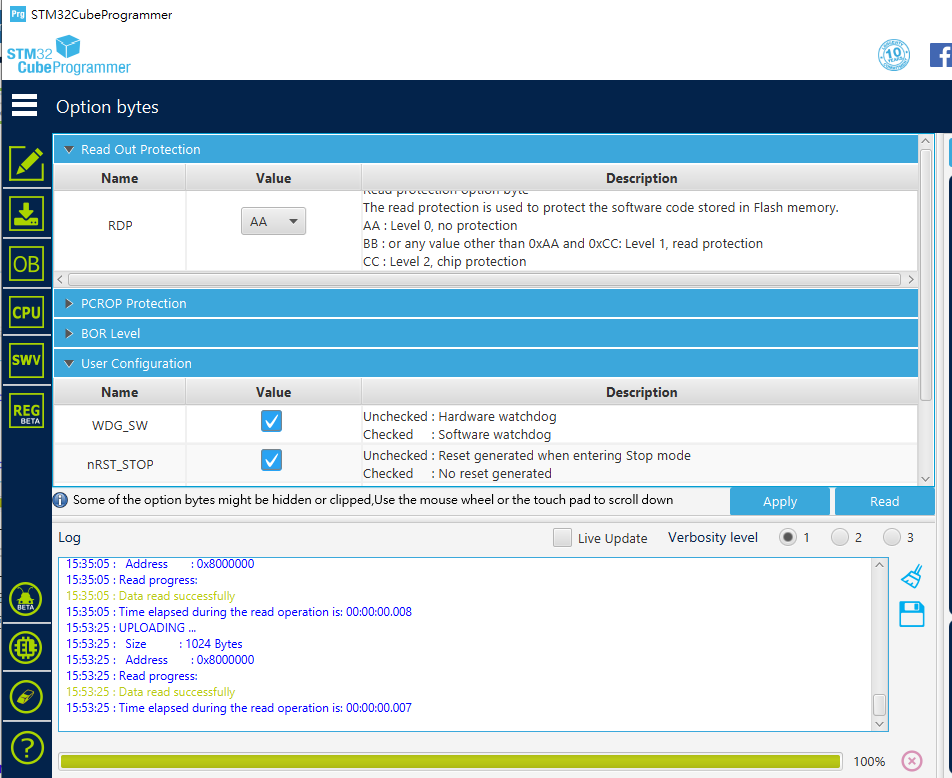
The settings that require more attention in the above figure are Read Out Protection and User Configuration. RDP is usually set to AA, and setting it to BB can prevent external programs from reading the internal program. However, it is important to note that if CC is irreversible. Once it is set to CC and burned into the MCU, it is equivalent to burning the bridge and cannot be used to read or burn other programs. PS: Setting BB back to AA will trigger the erasure of all Flash data, so setting BB can prevent program theft.
In User Configuration, the most commonly used settings are Boot0/Boot1 and IWDG. Each MCU may have slightly different settings in this area, so it is important to read its reference manual in detail. When modifying Option Bytes, remember not to power off midway (this may cause system errors and may make the Option Bytes disorderly and unrecoverable). After the modification is completed, power off and restart the MCU to ensure that the system actually receives the new settings.
STM32CubeProgram Command Line
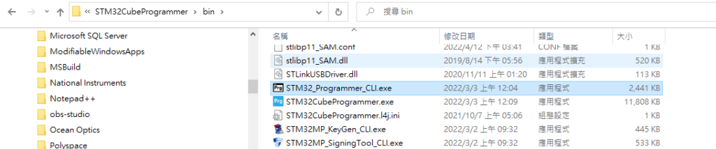
ST provides two versions for opening CubeProgram. The CLI version is shown in the following figure, and you can find the command section in the Bin folder for reference to the ST official document UM2237. Here is a solution for when IWDG settings fail and cannot be modified in the Option Bytes normally (using G031 as an example).
.\STM32_Programmer_CLI.exe -c port=swd mode=UR -ob rdp=1 //RDP 設定為level1 (0xBB)
.\STM32_Programmer_CLI.exe -c port=swd mode=UR -ob rdp=0xAA //再把RDP改回AA使其強制洗掉全部Flash內容
.\STM32_Programmer_CLI.exe -c port=swd mode=UR -ob WRP1A_STRT=31 WRP1A_END=0 //WRP 設定復歸
.\STM32_Programmer_CLI.exe -c port=swd mode=UR –ob NRST_MODE=3 // NRST_MODE設定復歸
.\STM32_Programmer_CLI.exe -c port=swd mode=UR –ob nBOOT0=1
.\STM32_Programmer_CLI.exe -c port=swd mode=UR –ob nBOOT1=1
.\STM32_Programmer_CLI.exe -c port=swd mode=UR –ob nBOOT_SEL=1
.\STM32_Programmer_CLI.exe -c port=swd mode=UR –ob WWDG_SW=1
.\STM32_Programmer_CLI.exe -c port=swd mode=UR –ob IWDG_STDBY=1
.\STM32_Programmer_CLI.exe -c port=swd mode=UR –ob IWDG_STOP=1
.\STM32_Programmer_CLI.exe -c port=swd mode=UR –ob IWDG_SW=1
After executing the above steps, there is a chance to recover the MCU.