

STM32WB LPTIM counter(Timing)
Preface
In STM32, some newer MCU models are equipped with LPTIM timers. For example, high-performance MCUs such as STM32F7 and H7, low-power MCUs such as STM32L0 and L4, as well as the newly released G0 and G4 series, all have this type of LPTIM timer. You can download the corresponding datasheet to see which MCUs are equipped with LPTIM. This article focuses on the LPTIM timer in the STM32WB.
LPTIM block diagram
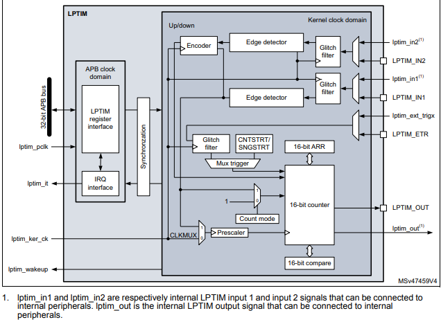
Compared to other timers in STM32, the RCC (Reset and Clock Control) function of LPTIM is more feature-rich. As shown in the diagram above, LPTIM can be clocked by multiple clock sources. It can be clocked by an internal clock signal, which can be selected from the APB, LSI, LSE, or HSI clock sources through the RCC (Reset and Clock Control) controller.
Low Power Timer Clock Selection Issue (Important)
1、lptim_ker_ck interface
The internal clock used by LPTIM. The lptim_ker_ck is connected to one input of the CLKMUX dual selector, while the other input is either LPTIM_IN1 or LPTIM_IN2. This means that the LPTIM counter can be driven by either lptim_ker_ck, LPTIM_IN1, or LPTIM_IN2.
2、The most critical part is here:
(1) The CLKMUX selector corresponds to bit0: CKSEL of the CFGR register, which is used to control the clock source for the internal clock. The clock can be provided by either an internal clock source (APB clock, LSE, LSI, HSI, or any other built-in oscillator) or by an external clock source via LPTIM external input.
(2) The count mode corresponds to bit23: COUNTMODE of the CFGR register, which is used to select the clock source for the LPTIM counter. The counter can be incremented either after each internal clock pulse or after each valid clock pulse on the LPTIM external input.
3、When using LPTIM, we can select:
(1) CKSEL = 0, COUNTMODE = 0, indicating that the LPTIM internal clock uses the internal clock source, and the counter counts via the internal clock pulse.
(2) CKSEL = 0, COUNTMODE = 1, indicating that the LPTIM internal clock uses the internal clock source, and the counter counts via the external input pulse.
(3) CKSEL = 1, COUNTMODE = x, indicating that the LPTIM internal clock uses the external clock source, and the counter counts via the external input pulse.
Timer handle structure LPTIM_HandleTypeDef
The clock source parameter ‘Source’ can be selected in the following two ways:
- #define LPTIM_CLOCKSOURCE_APBCLOCK_LPOSC ((uint32_t)0x00U)
- Indicates that LPTIM is clocked by an internal clock source (APB clock, LSE, LSI, HSI, etc.).
- #define LPTIM_CLOCKSOURCE_ULPTIM LPTIM_CFGR_CKSEL
- Indicates that LPTIM is clocked by an external clock source via LPTIM external Input1.
One-shot mode

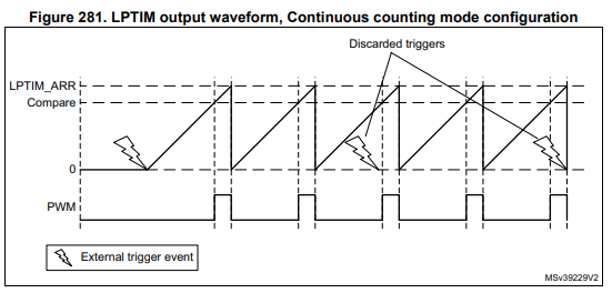
Continous mode
Timeout function
The detection of an active edge on one selected trigger input can be used to reset the LPTIM counter. This feature is controlled through the TIMOUT bit.
The first trigger event will start the timer, any successive trigger event will reset the counter and the timer will restart.
Timeout
/* ### Start the Timeout function in interrupt mode ################# */
  /*
   *  Period = 65535
   *  Pulse  = 32767
   *  According to this configuration (LPTIMER clocked by LSE & compare = 32767,
   *  the Timeout period = (compare + 1)/LSE_Frequency = 1s
   */
  if (HAL_LPTIM_TimeOut_Start_IT(&hlptim1, PERIOD, TIMEOUT) != HAL_OK)
  {
    Error_Handler();
  }
//will use this call back function
void HAL_LPTIM_CompareMatchCallback(LPTIM_HandleTypeDef *hlptim)
PulseCounter
/* ### Start counting in interrupt mode ############################# */
  /*
   *  Period = 1000
   */
  if (HAL_LPTIM_Counter_Start_IT(&hlptim1, 1000) != HAL_OK)
  {
    Error_Handler();
  }

//will use this call back function
void HAL_LPTIM_AutoReloadMatchCallback(LPTIM_HandleTypeDef *hlptim)